
Analyzing your prompt, please hold on...
An error occurred while retrieving the results. Please refresh the page and try again.
The <path> element draws the outline of any shape by combining lines, arcs, and Bézier curves. It is the most flexible SVG element for creating both simple and complex open or closed paths. A path is defined by a single d attribute that contains a series of commands.
In this article, you will learn to:
d attribute.A command to draw SVG arcs.T and S when curve segments must connect cleanly.| Command Group | Commands | Description |
|---|---|---|
| Moveto | M, m | Sets the starting point of a new sub-path. |
| Lineto | L, l, H, h, V, v | Draws straight lines horizontally, vertically, or to any coordinate. |
| Closepath | Z, z | Closes the current sub-path by linking back to its start point. |
| Cubic Bézier | C, c, S, s | Draws cubic Bézier curves with two control points. |
| Quadratic Bézier | Q, q, T, t | Draws quadratic Bézier curves with one control point. |
| Elliptical Arc | A, a | Draws elliptical arcs using radii, rotation, and flag parameters. |
Uppercase commands use absolute coordinates; lowercase commands use relative coordinates. All coordinates are unitless and are interpreted in the current SVG user coordinate system. A useful way to read path data is to imagine a current point that moves through the path: M sets where drawing begins, every drawing command leaves the current point at a new endpoint, and the next command starts from there.
<path> element and write its geometry in the d attribute.M x y to move the current point to the beginning of the path.L, H, V, A, Q, or C.Z when the path must become a filled shape.fill, stroke, and stroke-width to make the path visible.M, m)Any SVG path begins with the moveto command, written as M x y. The x and y coordinates indicate the current point where the path should start.
M x y (absolute) or m dx dy (relative).L, l, H, h, V, v)Three lineto commands draw straight lines from the current point to the new one:
| Command | Parameters | Description |
|---|---|---|
L / l | x y | Draw a line to the specified point. |
H / h | x | Draw a horizontal line; y remains unchanged. |
V / v | y | Draw a vertical line; x remains unchanged. |
After each path command, the current point moves to that command’s endpoint. The next drawing command starts from this new position.
Z, z)The Z closepath command closes the current sub-path by drawing a straight line back to its starting point. No parameters are required.
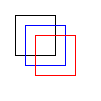
Let’s draw a square using lineto commands (
lineto.svg):
1<svg height="400" width="400" viewBox="0 0 200 200" xmlns="http://www.w3.org/2000/svg">
2    <path d="M 30 30 L 110 30 L 110 110 L 30 110 L 30 30" fill="transparent" stroke-width="2" stroke="black" />
3    <path d="M 50 50 H 130 V 130 H 50 Z" fill="transparent" stroke-width="2" stroke="blue" />
4    <path d="M 70 70 h 80 v 80 h -80 Z" fill="transparent" stroke-width="2" stroke="red" />
5</svg>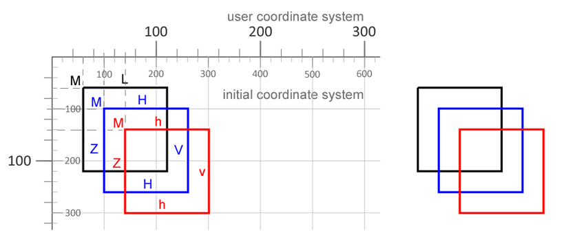
L command for each side.H and V for a more compact path, ending with Z.h and v commands.In the illustration, the left side annotates the path commands, and the right side shows the rendered SVG output. This makes it easier to compare three ways to draw the same square: explicit L commands, compact H and V commands, and relative lowercase commands.
Arcs draw sections of circles or ellipses. The A command needs six parameters that decide which of the four possible arcs between two points will be rendered.
Note: The same start point and endpoint can be connected by four different arcs. The large-arc-flag chooses the small or large arc, and the sweep-flag chooses the drawing direction.
Syntax: A rx ry x-axis-rotation large-arc-flag sweep-flag x y
| Parameter | Meaning |
|---|---|
rx, ry | Radii of the ellipse. |
x-axis-rotation | Rotation of the ellipse’s x-axis (degrees). |
large-arc-flag | 0 = small arc, 1 = large arc. |
sweep-flag | 0 = counter-clockwise, 1 = clockwise. |
x y | Absolute coordinates of the arc’s endpoint. |
The lowercase a works the same way but treats the endpoint as relative to the current point.
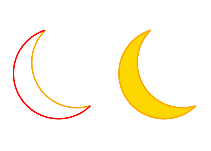
1<svg height="500" width="700" viewBox="0 0 100 100" xmlns="http://www.w3.org/2000/svg">
2    <path d="M10,20 A 30,30 0 0,0 40,70" style="stroke:#FFA500; stroke-width:1; fill:none" />
3    <path d="M10,20 A 30,30 0 1 0 40,70" style="stroke: #FF0000; stroke-width:1; fill:none" />
4    <path d="M10,20 A 30,30 0 0 0 40,70 A 30,30 0 1 1 10,20" style="stroke: #FFA500; stroke-width:1; fill:#FFD700" transform="translate(70,0)" />
5</svg>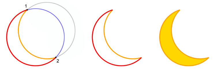
The illustration compares a small arc, a large arc, and a closed arc-based shape. The geometry starts from the same idea, but changing the arc flags changes which curve SVG chooses between the start and end points.
Consider this path from the code sample: d="M10,20 A 30,30 0 0,0 40,70".
M sets the start point (10, 20).A draws an arc to (40, 70) with a radius of 30, a small-arc flag of 0, and a sweep-flag of 0, resulting in a counter-clockwise (negative-angle) arc. This produces the gold-colored arc shown (
svg-arc.svg).Bézier curves are used to draw smooth outlines in icons, logos, illustrations, and diagrams. SVG paths support two Bézier curve types: quadratic curves with one control point and cubic curves with two control points. The start point comes from the current path position, the endpoint finishes the segment, and the control points pull the curve into shape.
A quadratic Bézier curve starts at the current point. The Q command then uses one control point (x1 y1) and one endpoint (x y). The lowercase q command has the same meaning, but its coordinates are relative to the current point.
Q, q, T, t)Quadratic Bézier curves use a single control point.
Q x1 y1 x y – absolute coordinates.q dx1 dy1 dx dy – relative coordinates.T x y – smooth continuation; the control point is inferred as the reflection of the previous one.t dx dy – relative version of T.Let’s consider an example:
1<svg width="600" height="600" viewBox="0 0 200 200" xmlns="http://www.w3.org/2000/svg">
2    <path d="M 10 100 Q 25 10 180 100" stroke="black" stroke-width="1" fill="transparent" />
3</svg>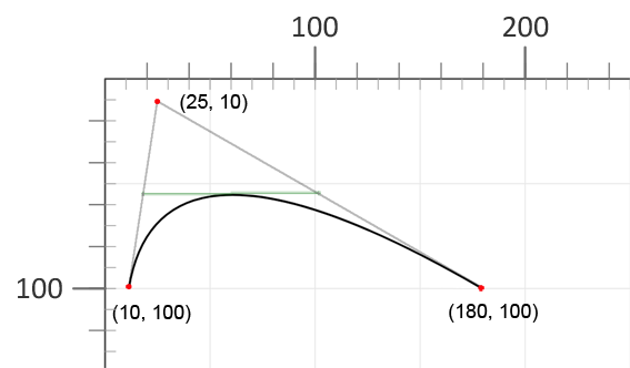
The curve starts at (10, 100), bends toward the control point (25, 10), and ends at (180, 100). Moving the control point changes the curve without changing its start or end point.
If you connect the control point to the start and endpoints of the curve with segments, the line connecting the centers of the segments will be tangent to the curve vertex.
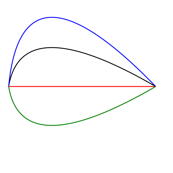
The next example keeps the same start and end points but changes the y1 coordinate of the control point ( bezier-curve2.svg). This shows how moving the control point up or down changes the bend of the curve:
1<svg width="600" height="600" viewBox="0 0 200 200" xmlns="http://www.w3.org/2000/svg">
2    <g stroke-width="1" fill="none">
3        <path d="M 10 100 Q 25 10 180 100" stroke="black" />
4        <path d="M 10 100 Q 25 -60 180 100" stroke="blue" />
5        <path d="M 10 100 Q 25 100 180 100" stroke="red" />
6        <path d="M 10 100 Q 25 190 180 100" stroke="green" />
7    </g>
8</svg>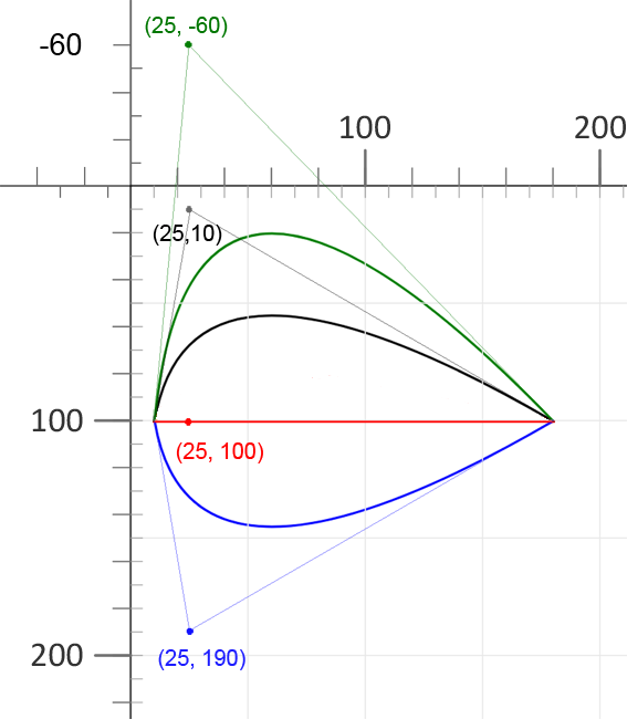
All four paths use the same start and end points. Only the vertical position of the control point changes, so the curve bends above, toward, or below the baseline.
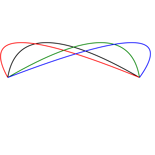
Now take the black curve as a basis and change the x1 coordinate of the control point ( bezier-curve3.svg):
1<svg width="600" height="600" viewBox="0 0 200 200" xmlns="http://www.w3.org/2000/svg">
2    <g stroke-width="1" fill="none">
3        <path d="M 10 100 Q 25 10 180 100" stroke="black" />
4        <path d="M 10 100 Q -40 10 180 100" stroke="red" />
5        <path d="M 10 100 Q 165 10 180 100" stroke="green" />
6        <path d="M 10 100 Q 245 10 180 100" stroke="blue" />
7    </g>
8</svg>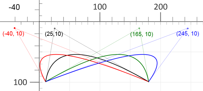
Here the control point moves left or right. This changes where the curve starts to bend, while the endpoint remains the same.
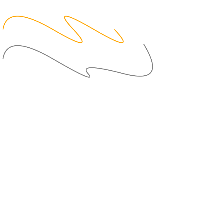
T1<svg width="700" height="600" xmlns="http://www.w3.org/2000/svg">
2 <path d="M 10 100 Q 25 10 180 100 T 250 100 T 320 100 T 390 100" stroke="orange" stroke-width="3" fill="none" />
3 <path d="M 10 200 Q 25 110 180 200 T 300 250 T 420 250 T 490 150" stroke="grey" stroke-width="3" fill="none" />
4</svg>Several Q commands can be written one after another, but the joins may look uneven if each segment uses an independent control point. Use the T command when you want SVG to continue a quadratic Bézier curve smoothly.
The T command draws from the current point to a new endpoint (x y). It does not take an explicit control point. Instead, SVG reflects the previous quadratic control point, but only when the previous command was Q or T. After T finishes, its endpoint becomes the new current point.
The example below uses the T command to continue a smooth quadratic curve. The x coordinates move at equal intervals, while the y coordinate remains unchanged.
1<svg width="700" height="600" xmlns="http://www.w3.org/2000/svg">
2    <path d="M 10 100 Q 25 10 180 100 T 350 100 T 520 100 T 690 100" stroke="black" stroke-width="3" fill="none" />
3</svg>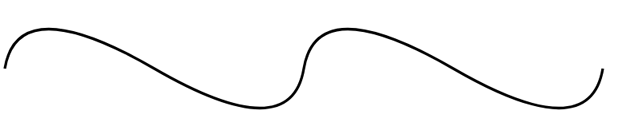
Changing the endpoint coordinates of the T command produces different smooth curve chains (
bezier-curve5.svg).
1<svg height="700" width="750" xmlns="http://www.w3.org/2000/svg">
2    <path d="M 10 100 Q 25 10 180 100 T 250 100 T 320 100 T 390 100" stroke="#FFA500" stroke-width="3" fill="none" />
3    <path d="M 10 200 Q 25 110 180 200 T 300 250 T 420 250 T 490 150" stroke="grey" stroke-width="3" fill="none" />
4</svg>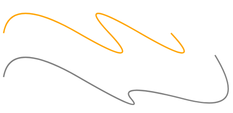
C, c, S, s)Cubic Bézier curves require two control points. The C command takes three coordinate pairs: the first control point (x1 y1), the second control point (x2 y2), and the endpoint (x y).
C x1 y1 x2 y2 x y – absolute coordinates.c dx1 dy1 dx2 dy2 dx dy – relative coordinates.The control points determine the direction of the curve near its start and end. You can write several C commands in one <path> element; SVG draws them sequentially, and the endpoint of one cubic curve becomes the start point of the next curve.
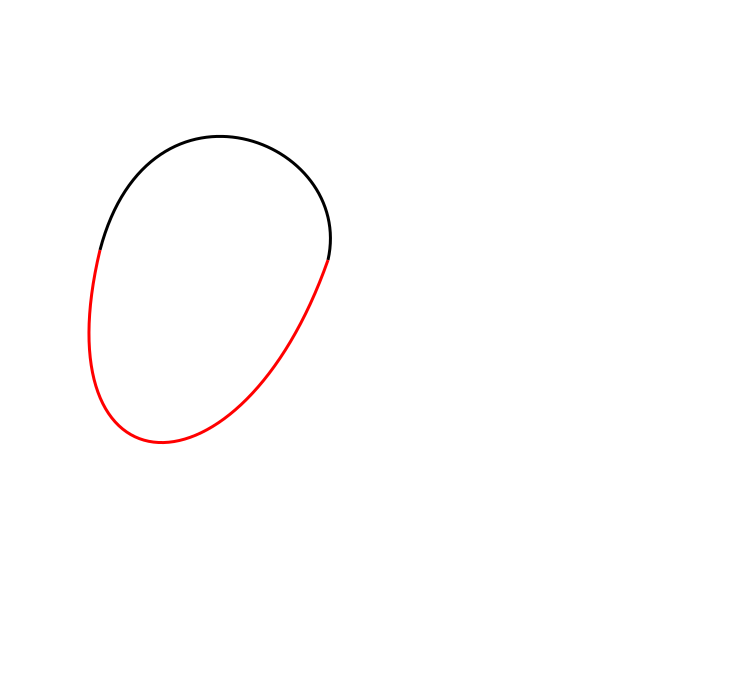
The following example draws a shape with two separate cubic Bézier paths ( cubic-bezier-curves.svg):
1<svg height="700" width="750" xmlns="http://www.w3.org/2000/svg">
2    <!--shape two paths-->
3    <path d="M 100 250 C 150 60 355 140 328 260 " stroke="black" stroke-width="3" fill="none" />
4    <path d="M 100 250 C 40 500 240 510 328 260" stroke="red" stroke-width="3" fill="none" />
5</svg>
The illustration shows the two separate cubic Bézier paths in black and red, so the connection between the curve segments is easy to inspect.
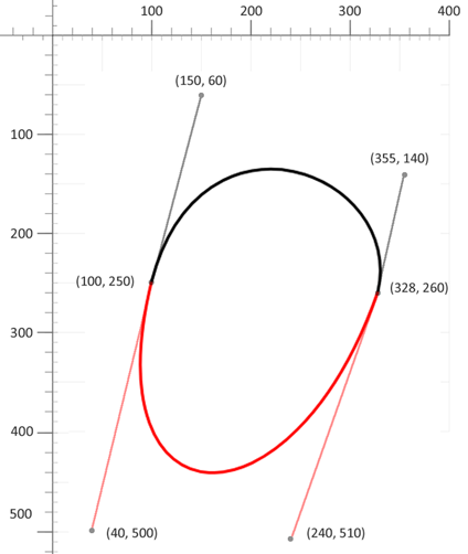
The next example draws the same outline as one continuous path:
1<svg height="700" width="750" xmlns="http://www.w3.org/2000/svg">
2   <!--shape 1 path-->
3   <path d="M 100 250 C 150 60 355 140 328 260 C 240 510 40 500 100 250" stroke="black" stroke-width="3" fill="none" />
4</svg>
In the sample above, two C commands are connected inside one path. This is compact, but the connection point can look less smooth if the control points do not preserve the same direction.
SFor long smooth curves, use the S x2 y2 x y shortcut command. Like T for quadratic curves, S continues a cubic Bézier chain without requiring you to write the first control point explicitly.
For the S command, SVG reflects the previous cubic control point to keep the slope continuous. You only provide the second control point (x2 y2) and the endpoint (x y).
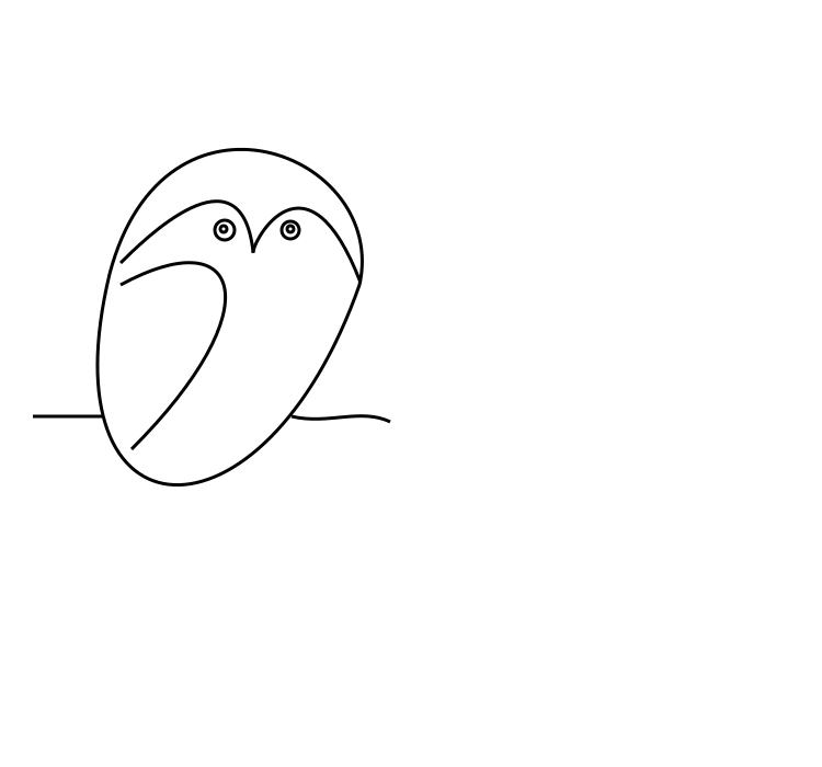
S x2 y2 x y – smooth cubic; the first control point is reflected from the previous segment.s dx2 dy2 dx dy – relative version of S.Bézier curves can also be combined into expressive drawings. The example below uses simple path segments and circles to create a primitive-style owl illustration ( owl.svg):
 1<svg height="700" width="750" xmlns="http://www.w3.org/2000/svg">
 2    <g stroke="black" stroke-width="3" fill="none">
 3        <!--body 1 path-->
 4        <path d="M 100 250 C 150 60 355 140 328 260 C 240 510 40 500 100 250" />
 5        <!--wing-->
 6        <path d="M 110 260 C 220 200, 250 280, 120 410" />
 7        <!--1 eyebrow-->
 8        <path d="M 110 240 C 130 220, 220 130, 231 230" />
 9        <!--2 eyebrow-->
10        <path d="M 231 231 C 230 220, 280 130, 329 258" />
11        <!--line-->
12        <path d="M 30 380 l 63 0" />
13        <path d="M 266 380 c 33 8 63 -8 90 5" />
14        <!--eyes-->
15        <circle cx="204" cy="209" r="3" />
16        <circle cx="205" cy="210" r="9" />
17        <circle cx="265" cy="209" r="3" />
18        <circle cx="265" cy="210" r="8" />
19    </g>
20</svg>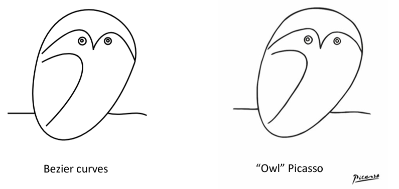
| Problem | Cause | Fix |
|---|---|---|
| The path is not rendered | The path data does not start with a M command | Always begin the d attribute with M x y to define the starting point |
| The shape is not closed | The Z command is missing | Add Z at the end of the path to close the sub-path |
| The arc is drawn in an unexpected direction | Incorrect large-arc-flag or sweep-flag values | Toggle one flag at a time (0 or 1) and visually verify the result |
The T command does not produce a smooth curve | The previous command was not Q or T | Use T only after a Q or another T command |
| Sharp corners appear between cubic Bézier segments | Consecutive C commands are used | Use the S command to create smooth cubic Bézier chains |
| The path shifts unexpectedly | Absolute and relative commands are mixed unintentionally | Check command case: uppercase for absolute, lowercase for relative |
| The shape is not filled | The path is open or fill="none" is set | Close the path with Z and verify the fill attribute |
| Task | SVG Path Example |
|---|---|
| Draw a rectangle | <path d="M10 10 H110 V110 H10 Z" fill="none" stroke="black" /> |
| Close an open path | Append Z to the end of the d attribute |
| Draw a simple arc | <path d="M10 50 A30 30 0 0 1 90 50" fill="none" stroke="orange" /> |
| Draw a full circle using arcs | <path d="M50 10 A40 40 0 1 1 49.9 10 Z" /> |
| Draw a quadratic Bézier curve | <path d="M10 80 Q95 10 180 80" fill="none" stroke="black" /> |
| Create a smooth quadratic chain | <path d="M10 80 Q60 10 110 80 T210 80" /> |
| Draw a cubic Bézier curve | <path d="M10 80 C40 10 140 10 170 80" /> |
| Create a smooth cubic chain | <path d="M10 80 C40 10 140 10 170 80 S300 150 330 80" /> |
SVG path data is the command string stored in the d attribute of a <path> element. It tells SVG where to move, where to draw lines, how to draw arcs, and how to create Bézier curves.
Uppercase commands use absolute coordinates in the current user coordinate system. Lowercase commands use coordinates relative to the current point, which is useful for repeated segments and compact path data.
Use the Z or z command at the end of the sub-path. It draws a straight line from the current point back to the sub-path start and helps filled shapes render as closed outlines.
Use <path> when a rectangle, circle, ellipse, line, polyline, or polygon is not flexible enough. Paths are better for custom outlines, icons, logos, arcs, and smooth curves.
d attribute and all path commands.<path> elements.d string by hand.d attribute, replace path geometry, and build paths from ordinary coordinates.
Analyzing your prompt, please hold on...
An error occurred while retrieving the results. Please refresh the page and try again.