
Analyzing your prompt, please hold on...
An error occurred while retrieving the results. Please refresh the page and try again.
<path> 元素通过组合线条、圆弧和 Bézier 曲线来绘制任意形状的轮廓。它是 SVG 中最灵活的元素,可创建简单或复杂的开放路径与闭合路径。一个 path 由单个 d 属性定义,其中包含一系列命令。
本文将学习:
d 属性中最常见的 SVG path commands。A command 绘制 SVG arcs。T 和 S 等 smooth commands。| 命令组 | 命令 | 说明 |
|---|---|---|
| Moveto | M, m | 设置新 sub-path 的起点。 |
| Lineto | L, l, H, h, V, v | 水平、垂直或向任意坐标绘制直线。 |
| Closepath | Z, z | 通过连接回起点来闭合当前 sub-path。 |
| Cubic Bézier | C, c, S, s | 使用两个控制点绘制三次 Bézier 曲线。 |
| Quadratic Bézier | Q, q, T, t | 使用一个控制点绘制二次 Bézier 曲线。 |
| Elliptical Arc | A, a | 使用半径、旋转和 flag 参数绘制椭圆弧。 |
大写命令使用绝对坐标;小写命令使用相对坐标。所有坐标本身不带单位,并在当前 SVG 用户坐标系统中解释。读取 path data 的一个实用方法,是想象有一个 current point 沿路径移动:M 设置绘图开始位置,每个绘制命令都会把 current point 留在新的终点,下一个命令从那里开始。
<path> 元素,并在 d 属性中写入几何命令。M x y 开始,把 current point 移动到路径起点。L、H、V、A、Q 或 C。Z 闭合轮廓。fill、stroke 和 stroke-width,使 path 可见。M, m)任何 SVG path 都以 moveto 命令开始,写作 M x y。x 和 y 坐标表示路径开始的 current point。
M x y(绝对)或 m dx dy(相对)。L, l, H, h, V, v)三个 lineto 命令从 current point 向新点绘制直线:
| 命令 | 参数 | 说明 |
|---|---|---|
L / l | x y | 向指定点绘制一条线。 |
H / h | x | 绘制水平线;y 保持不变。 |
V / v | y | 绘制垂直线;x 保持不变。 |
每个 path command 执行后,current point 会移动到该命令的终点。下一个绘制命令从这个新位置开始。
Z, z)Z closepath command 通过绘制一条直线回到 sub-path 起点来闭合当前 sub-path。不需要参数。
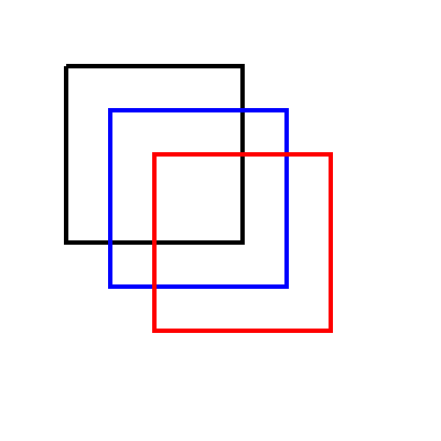
下面用 lineto commands 绘制正方形(
lineto.svg):
1<svg height="400" width="400" viewBox="0 0 200 200" xmlns="http://www.w3.org/2000/svg">
2    <path d="M 30 30 L 110 30 L 110 110 L 30 110 L 30 30" fill="transparent" stroke-width="2" stroke="black" />
3    <path d="M 50 50 H 130 V 130 H 50 Z" fill="transparent" stroke-width="2" stroke="blue" />
4    <path d="M 70 70 h 80 v 80 h -80 Z" fill="transparent" stroke-width="2" stroke="red" />
5</svg>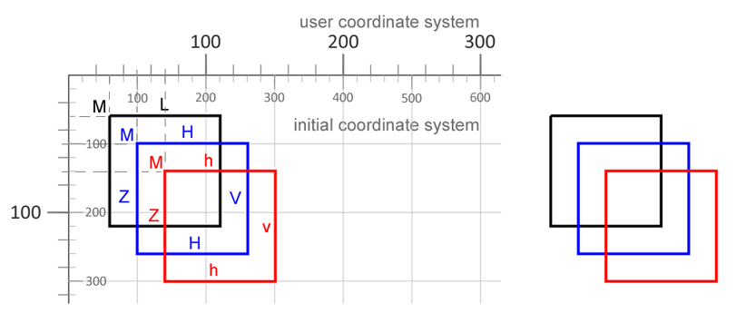
L command。H 和 V,并以 Z 结束。h 和 v。图中左侧标注 path commands,右侧显示渲染结果,便于比较三种绘制同一正方形的方式:显式 L 命令、紧凑 H/V 命令和相对小写命令。
Arcs 绘制圆或椭圆的一段。A command 需要六个参数,用来决定两点之间四种可能圆弧中的哪一种被渲染。
注意: 同一个起点和终点可以由四条不同圆弧连接。large-arc-flag 选择小弧或大弧,sweep-flag 选择绘制方向。
语法: A rx ry x-axis-rotation large-arc-flag sweep-flag x y
| 参数 | 含义 |
|---|---|
rx, ry | 椭圆半径。 |
x-axis-rotation | 椭圆 x 轴的旋转角度(度)。 |
large-arc-flag | 0 表示小弧,1 表示大弧。 |
sweep-flag | 0 表示逆时针,1 表示顺时针。 |
x y | 圆弧终点的绝对坐标。 |
小写 a 的工作方式相同,但终点相对于 current point。
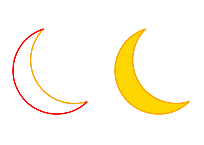
1<svg height="500" width="700" viewBox="0 0 100 100" xmlns="http://www.w3.org/2000/svg">
2    <path d="M10,20 A 30,30 0 0,0 40,70" style="stroke:#FFA500; stroke-width:1; fill:none" />
3    <path d="M10,20 A 30,30 0 1 0 40,70" style="stroke: #FF0000; stroke-width:1; fill:none" />
4    <path d="M10,20 A 30,30 0 0 0 40,70 A 30,30 0 1 1 10,20" style="stroke: #FFA500; stroke-width:1; fill:#FFD700" transform="translate(70,0)" />
5</svg>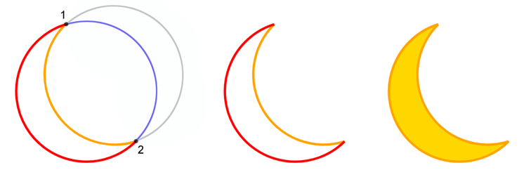
图示比较小弧、大弧和基于圆弧闭合的形状。几何从同一思路开始,但改变 arc flags 会改变 SVG 在起点和终点之间选择哪条曲线。
看这段 path:d="M10,20 A 30,30 0 0,0 40,70"。
M 设置起点 (10, 20)。A 用半径 30、小弧 flag 为 0、sweep flag 为 0 绘制到 (40, 70) 的圆弧,得到逆时针(负角度)圆弧,也就是图中的金色圆弧(
svg-arc.svg)。Bézier curves 用于在图标、徽标、插图和图表中绘制平滑轮廓。SVG paths 支持两种 Bézier 曲线:一个控制点的二次曲线和两个控制点的三次曲线。起点来自当前 path 位置,终点结束该段,控制点把曲线拉成所需形状。
二次 Bézier curve 从 current point 开始。Q command 使用一个控制点 (x1 y1) 和一个终点 (x y)。小写 q 含义相同,但坐标相对于 current point。
Q, q, T, t)二次 Bézier curves 使用一个控制点。
Q x1 y1 x y – 绝对坐标。q dx1 dy1 dx dy – 相对坐标。T x y – 平滑延续;控制点会推断为前一个控制点的镜像。t dx dy – T 的相对版本。示例:
1<svg width="600" height="600" viewBox="0 0 200 200" xmlns="http://www.w3.org/2000/svg">
2    <path d="M 10 100 Q 25 10 180 100" stroke="black" stroke-width="1" fill="transparent" />
3</svg>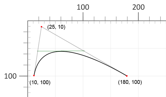
曲线从 (10, 100) 开始,向控制点 (25, 10) 弯曲,并在 (180, 100) 结束。移动控制点会改变曲线形状,但不改变起点或终点。
如果用线段连接控制点与曲线的起点和终点,连接这些线段中心的线会与曲线顶点相切。
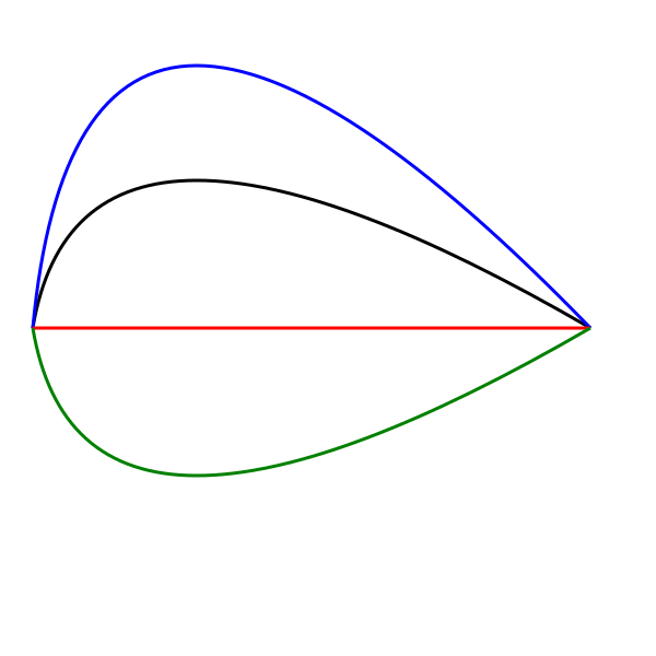
下一个示例保持相同起点和终点,只改变控制点的 y1 坐标( bezier-curve2.svg)。它展示控制点上下移动如何改变曲线弯曲方式:
1<svg width="600" height="600" viewBox="0 0 200 200" xmlns="http://www.w3.org/2000/svg">
2    <g stroke-width="1" fill="none">
3        <path d="M 10 100 Q 25 10 180 100" stroke="black" />
4        <path d="M 10 100 Q 25 -60 180 100" stroke="blue" />
5        <path d="M 10 100 Q 25 100 180 100" stroke="red" />
6        <path d="M 10 100 Q 25 190 180 100" stroke="green" />
7    </g>
8</svg>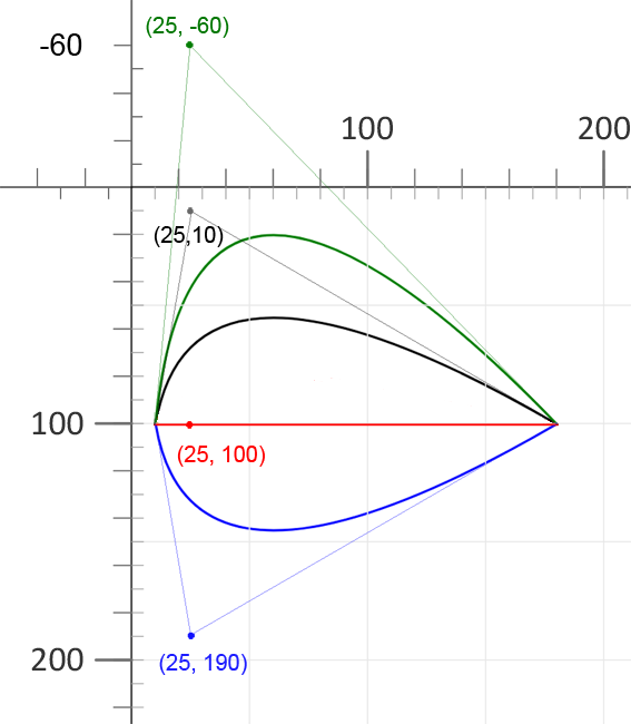
四个 paths 使用相同起点和终点。只有控制点的垂直位置改变,因此曲线会向基线之上、靠近基线或基线之下弯曲。
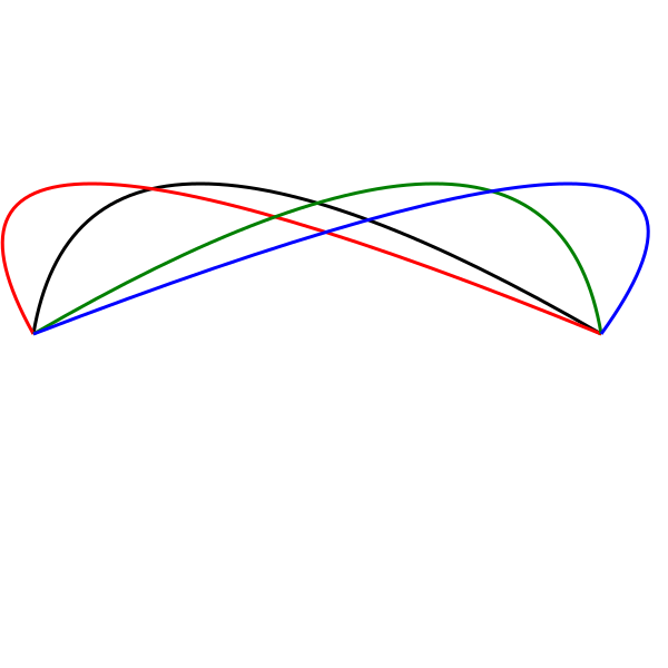
现在以黑色曲线为基础,改变控制点的 x1 坐标( bezier-curve3.svg):
1<svg width="600" height="600" viewBox="0 0 200 200" xmlns="http://www.w3.org/2000/svg">
2    <g stroke-width="1" fill="none">
3        <path d="M 10 100 Q 25 10 180 100" stroke="black" />
4        <path d="M 10 100 Q -40 10 180 100" stroke="red" />
5        <path d="M 10 100 Q 165 10 180 100" stroke="green" />
6        <path d="M 10 100 Q 245 10 180 100" stroke="blue" />
7    </g>
8</svg>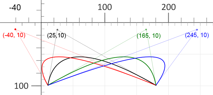
这里控制点向左或向右移动。它改变曲线开始弯曲的位置,而终点保持不变。
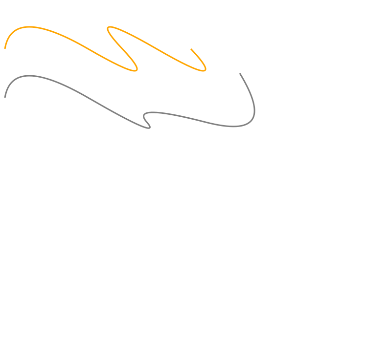
T 创建平滑链1<svg width="700" height="600" xmlns="http://www.w3.org/2000/svg">
2 <path d="M 10 100 Q 25 10 180 100 T 250 100 T 320 100 T 390 100" stroke="orange" stroke-width="3" fill="none" />
3 <path d="M 10 200 Q 25 110 180 200 T 300 250 T 420 250 T 490 150" stroke="grey" stroke-width="3" fill="none" />
4</svg>多个 Q command 可以连续书写,但如果每段使用独立控制点,连接处可能不够平滑。当你希望 SVG 平滑延续二次 Bézier 曲线时,使用 T command。
T command 从 current point 绘制到新终点 (x y)。它不接受显式控制点,而是让 SVG 反射前一个二次控制点,但前一个命令必须是 Q 或 T。T 完成后,其终点成为新的 current point。
1<svg width="700" height="600" xmlns="http://www.w3.org/2000/svg">
2    <path d="M 10 100 Q 25 10 180 100 T 350 100 T 520 100 T 690 100" stroke="black" stroke-width="3" fill="none" />
3</svg>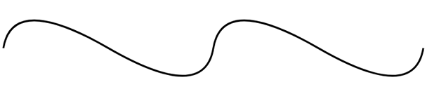
改变 T command 的终点坐标会产生不同的平滑曲线链(
bezier-curve5.svg)。
1<svg height="700" width="750" xmlns="http://www.w3.org/2000/svg">
2    <path d="M 10 100 Q 25 10 180 100 T 250 100 T 320 100 T 390 100" stroke="#FFA500" stroke-width="3" fill="none" />
3    <path d="M 10 200 Q 25 110 180 200 T 300 250 T 420 250 T 490 150" stroke="grey" stroke-width="3" fill="none" />
4</svg>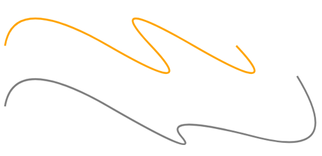
C, c, S, s)三次 Bézier curves 需要两个控制点。C command 接受三组坐标:第一个控制点 (x1 y1)、第二个控制点 (x2 y2) 和终点 (x y)。
C x1 y1 x2 y2 x y – 绝对坐标。c dx1 dy1 dx2 dy2 dx dy – 相对坐标。控制点决定曲线靠近起点和终点时的方向。你可以在一个 <path> 元素中写多个 C command;SVG 会按顺序绘制,一个三次曲线的终点成为下一段曲线的起点。
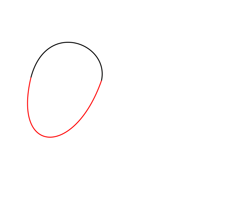
下面示例用两个独立的三次 Bézier paths 绘制形状( cubic-bezier-curves.svg):
1<svg height="700" width="750" xmlns="http://www.w3.org/2000/svg">
2    <!--shape two paths-->
3    <path d="M 100 250 C 150 60 355 140 328 260 " stroke="black" stroke-width="3" fill="none" />
4    <path d="M 100 250 C 40 500 240 510 328 260" stroke="red" stroke-width="3" fill="none" />
5</svg>
插图用黑色和红色显示两条独立的三次 Bézier paths,便于检查曲线段之间的连接。
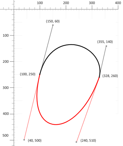
下一个示例把相同轮廓作为一个连续 path 绘制:
1<svg height="700" width="750" xmlns="http://www.w3.org/2000/svg">
2   <!--shape 1 path-->
3   <path d="M 100 250 C 150 60 355 140 328 260 C 240 510 40 500 100 250" stroke="black" stroke-width="3" fill="none" />
4</svg>
上面的示例在一个 path 内连接了两个 C commands。这种写法更紧凑,但如果控制点没有保持相同方向,连接点可能不够平滑。
S 创建平滑三次曲线链对于较长的平滑曲线,可以使用快捷命令 S x2 y2 x y。它类似二次曲线中的 T,可以延续三次 Bézier 链,而不需要显式写出第一个控制点。对于 S command,SVG 会反射前一段三次控制点来保持斜率连续。你只需提供第二个控制点 (x2 y2) 和终点 (x y)。
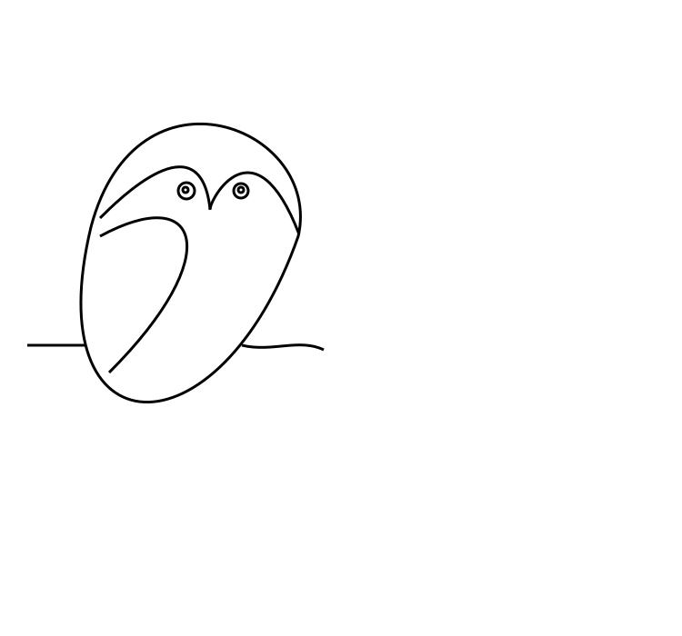
S x2 y2 x y – 平滑三次曲线;第一个控制点由前一段反射得到。s dx2 dy2 dx dy – S 的相对版本。Bézier curves 也可以组合成具有表现力的图形。下面的示例使用简单 path 段和圆创建 primitive-style 猫头鹰插图( owl.svg):
 1<svg height="700" width="750" xmlns="http://www.w3.org/2000/svg">
 2    <g stroke="black" stroke-width="3" fill="none">
 3        <!--body 1 path-->
 4        <path d="M 100 250 C 150 60 355 140 328 260 C 240 510 40 500 100 250" />
 5        <!--wing-->
 6        <path d="M 110 260 C 220 200, 250 280, 120 410" />
 7        <!--1 eyebrow-->
 8        <path d="M 110 240 C 130 220, 220 130, 231 230" />
 9        <!--2 eyebrow-->
10        <path d="M 231 231 C 230 220, 280 130, 329 258" />
11        <!--line-->
12        <path d="M 30 380 l 63 0" />
13        <path d="M 266 380 c 33 8 63 -8 90 5" />
14        <!--eyes-->
15        <circle cx="204" cy="209" r="3" />
16        <circle cx="205" cy="210" r="9" />
17        <circle cx="265" cy="209" r="3" />
18        <circle cx="265" cy="210" r="8" />
19    </g>
20</svg>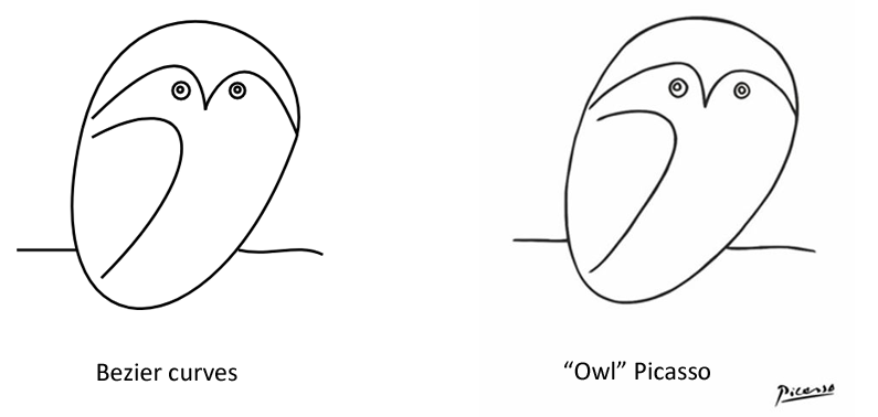
| 问题 | 原因 | 修复方法 |
|---|---|---|
| path 没有渲染 | path data 不是以 M command 开始 | 始终用 M x y 开始 d 属性,定义起点 |
| 形状没有闭合 | 缺少 Z command | 在 path 末尾添加 Z 闭合 sub-path |
| 圆弧方向不符合预期 | large-arc-flag 或 sweep-flag 值错误 | 每次切换一个 flag(0 或 1)并视觉确认结果 |
T command 没有产生平滑曲线 | 前一个命令不是 Q 或 T | 仅在 Q 或另一个 T command 之后使用 T |
| 三次 Bézier 段之间出现尖角 | 连续使用 C commands | 使用 S command 创建平滑三次 Bézier 链 |
| path 意外偏移 | 无意混用绝对和相对命令 | 检查命令大小写:大写表示绝对,小写表示相对 |
| 形状未填充 | path 是开放的,或设置了 fill="none" | 用 Z 闭合 path,并检查 fill 属性 |
| 任务 | SVG Path 示例 |
|---|---|
| 绘制矩形 | <path d="M10 10 H110 V110 H10 Z" fill="none" stroke="black" /> |
| 闭合开放 path | 在 d 属性末尾追加 Z |
| 绘制简单圆弧 | <path d="M10 50 A30 30 0 0 1 90 50" fill="none" stroke="orange" /> |
| 用 arcs 绘制完整圆 | <path d="M50 10 A40 40 0 1 1 49.9 10 Z" /> |
| 绘制二次 Bézier 曲线 | <path d="M10 80 Q95 10 180 80" fill="none" stroke="black" /> |
| 创建平滑二次曲线链 | <path d="M10 80 Q60 10 110 80 T210 80" /> |
| 绘制三次 Bézier 曲线 | <path d="M10 80 C40 10 140 10 170 80" /> |
| 创建平滑三次曲线链 | <path d="M10 80 C40 10 140 10 170 80 S300 150 330 80" /> |
SVG path data 是存储在 <path> 元素 d 属性中的命令字符串。它告诉 SVG 移动到哪里、在哪里绘制线条、如何绘制圆弧,以及如何创建 Bézier curves。
大写命令使用当前用户坐标系统中的绝对坐标。小写命令使用相对于 current point 的坐标,适合重复线段和更紧凑的 path data。
在 sub-path 末尾使用 Z 或 z command。它会从 current point 绘制直线回到 sub-path 起点,并帮助填充形状以闭合轮廓渲染。
当矩形、圆、椭圆、直线、折线或多边形不够灵活时,使用 <path>。Paths 更适合自定义轮廓、图标、徽标、圆弧和平滑曲线。
d 属性和所有 path commands。<path> 元素的 .NET API 示例。d 字符串。d 属性、替换 path geometry,以及从普通坐标构建 paths 的示例。
Analyzing your prompt, please hold on...
An error occurred while retrieving the results. Please refresh the page and try again.