
JavaScript를 사용하여 프레젠테이션에서 커넥터 관리
개요
커넥터는 두 개의 도형이 움직여도 두 도형에 연결된 상태를 유지할 수 있는 선입니다. 양쪽 끝은 PowerPoint에서 초록색 점으로 표시되는 연결 지점에 연결됩니다. 구부러지거나 곡선 형태의 커넥터 중 일부는 오렌지색 점으로 표시되는 조정점을 노출하여 각 커넥터 세그먼트의 위치를 제어할 수 있습니다.
Aspose.Slides는 커넥터를 Connector 클래스로 나타냅니다. 커넥터를 생성하고, 끝을 도형에 연결하고, 연결 지점을 선택하고, 재경로 지정하고, 조정점을 가진 커넥터의 기하학을 수정할 수 있습니다.
커넥터 유형
ShapeType 클래스에는 직선, 굽힘, 곡선 커넥터 프리셋이 포함됩니다. 아래 표는 사용 가능한 커넥터 기하학과 각 프리셋에 정의된 조정점 수를 보여줍니다.
| 커넥터 | Image | 조정점 수 |
|---|---|---|
ShapeType.Line |
 |
0 |
ShapeType.StraightConnector1 |
 |
0 |
ShapeType.BentConnector2 |
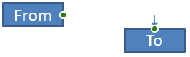 |
0 |
ShapeType.BentConnector3 |
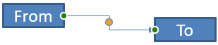 |
1 |
ShapeType.BentConnector4 |
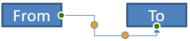 |
2 |
ShapeType.BentConnector5 |
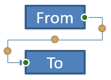 |
3 |
ShapeType.CurvedConnector2 |
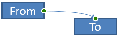 |
0 |
ShapeType.CurvedConnector3 |
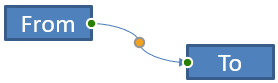 |
1 |
ShapeType.CurvedConnector4 |
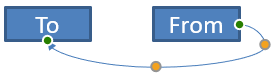 |
2 |
ShapeType.CurvedConnector5 |
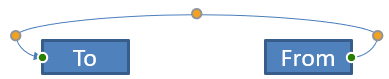 |
3 |
조정점의 수와 의미는 선택된 커넥터 프리셋의 일부입니다. 두 가지 다른 커넥터 유형이 동일한 컬렉션 레이아웃을 제공한다고 가정하지 마십시오.
두 도형 연결하기
ShapeCollection.addConnector을 사용해 커넥터를 추가하고, Connector.setStartShapeConnectedTo와 Connector.setEndShapeConnectedTo를 사용해 양쪽 끝을 연결합니다. 양쪽 끝이 연결된 후에는 Connector.reroute가 도형 사이의 짧은 경로를 선택합니다.
다음 예제는 타원과 사각형을 굽힌 커넥터로 연결합니다.
const aspose = { slides: require("aspose.slides.via.java") };

const presentation = new aspose.slides.Presentation();
try {
    const slide = presentation.getSlides().get_Item(0);

    const ellipse = slide.getShapes().addAutoShape(aspose.slides.ShapeType.Ellipse, 40, 80, 120, 80);
    const rectangle = slide.getShapes().addAutoShape(aspose.slides.ShapeType.Rectangle, 320, 240, 140, 80);
    const connector = slide.getShapes().addConnector(aspose.slides.ShapeType.BentConnector2, 0, 0, 10, 10);

    connector.setStartShapeConnectedTo(ellipse);
    connector.setEndShapeConnectedTo(rectangle);
    connector.reroute();

    presentation.save("connected-shapes.pptx", aspose.slides.SaveFormat.Pptx);
} finally {
    presentation.dispose();
}
경고
reroute를 호출하면 setStartShapeConnectionSiteIndex와 setEndShapeConnectionSiteIndex 값이 변경될 수 있습니다. 해당 사이트를 고정해야 한다면 재경로 지정 후에 특정 연결 지점을 지정하십시오.
연결 지점 선택하기
연결 가능한 각 도형은 Shape.getConnectionSiteCount를 통해 사이트 수를 보고합니다. 도형에 따라 사이트 수가 다르므로, 커넥터 끝에 할당하기 전에 선호하는 0 기반 사이트 인덱스를 검증하십시오.
다음 예제는 해당 사이트가 존재할 경우 타원의 특정 사이트에 커넥터를 연결합니다.
const aspose = { slides: require("aspose.slides.via.java") };

const presentation = new aspose.slides.Presentation();
try {
    const slide = presentation.getSlides().get_Item(0);

    const ellipse = slide.getShapes().addAutoShape(aspose.slides.ShapeType.Ellipse, 40, 80, 120, 80);
    const rectangle = slide.getShapes().addAutoShape(aspose.slides.ShapeType.Rectangle, 320, 240, 140, 80);
    const connector = slide.getShapes().addConnector(aspose.slides.ShapeType.BentConnector3, 0, 0, 10, 10);

    connector.setStartShapeConnectedTo(ellipse);
    connector.setEndShapeConnectedTo(rectangle);

    const preferredSiteIndex = 2;
    if (preferredSiteIndex < ellipse.getConnectionSiteCount()) {
        connector.setStartShapeConnectionSiteIndex(preferredSiteIndex);
    } else {
        console.log(`The ellipse has only ${ellipse.getConnectionSiteCount()} connection sites.`);
    }

    presentation.save("specific-connection-site.pptx", aspose.slides.SaveFormat.Pptx);
} finally {
    presentation.dispose();
}
커넥터 포인트 조정하기
조정점을 가진 커넥터는 GeometryShape.getAdjustments를 통해 노출됩니다. 각 AdjustValue를 검사하고, setRawValue로 변경하기 전에 getType 값을 확인하십시오. 프리셋 형태 조정 식별에 관한 일반 규칙은 Shape Manipulation에 설명되어 있습니다.
커넥터 조정의 개수, 순서, 의미 및 허용 값 범위는 커넥터 프리셋에 따라 다릅니다. 조정 유형은 읽기 전용이며, 조정 값은 쓰기 가능합니다. 동일한 의미 유형이 여러 개 존재할 때는 읽기 전용 getName 메서드가 추가 식별 정보를 제공합니다.
장애물 회피 경로
다음 레이아웃에서 BentConnector5 커넥터가 두 도형 사이에 세 번째 도형을 통과합니다.
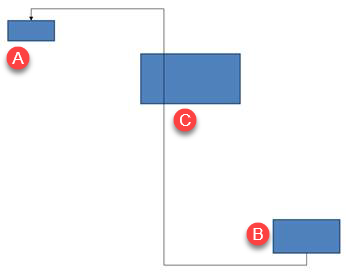
이 코드는 방해받는 커넥터를 생성합니다.
const aspose = { slides: require("aspose.slides.via.java") };
const java = require("java");

const presentation = new aspose.slides.Presentation();
try {
    const slide = presentation.getSlides().get_Item(0);

    slide.getShapes().addAutoShape(aspose.slides.ShapeType.Rectangle, 300, 150, 150, 75);
    const sourceShape = slide.getShapes().addAutoShape(aspose.slides.ShapeType.Rectangle, 500, 400, 100, 50);
    const targetShape = slide.getShapes().addAutoShape(aspose.slides.ShapeType.Rectangle, 100, 100, 70, 30);
    const connector = slide.getShapes().addConnector(aspose.slides.ShapeType.BentConnector5, 20, 20, 400, 300);

    const black = java.getStaticFieldValue("java.awt.Color", "BLACK");
    const solidFillType = java.newByte(aspose.slides.FillType.Solid);
    const triangleArrowheadStyle = java.newByte(aspose.slides.LineArrowheadStyle.Triangle);
    connector.getLineFormat().setEndArrowheadStyle(triangleArrowheadStyle);
    connector.getLineFormat().getFillFormat().setFillType(solidFillType);
    connector.getLineFormat().getFillFormat().getSolidFillColor().setColor(black);
    connector.setStartShapeConnectedTo(sourceShape);
    connector.setEndShapeConnectedTo(targetShape);
    connector.setStartShapeConnectionSiteIndex(2);

    presentation.save("connector-obstruction.pptx", aspose.slides.SaveFormat.Pptx);
} finally {
    presentation.dispose();
}
수직 굽힘을 이동하면 경로가 변경되어 커넥터가 장애물을 우회합니다.
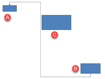
컬렉션 인덱스 1이 항상 수직 굽힘을 의미한다고 가정하지 말고, 이 예제는 ConnectorBendPositionY를 검색한 뒤 예상 의미 유형이 존재할 때만 변경합니다.
const aspose = { slides: require("aspose.slides.via.java") };
const java = require("java");

const presentation = new aspose.slides.Presentation();
try {
    const slide = presentation.getSlides().get_Item(0);

    slide.getShapes().addAutoShape(aspose.slides.ShapeType.Rectangle, 300, 150, 150, 75);
    const sourceShape = slide.getShapes().addAutoShape(aspose.slides.ShapeType.Rectangle, 500, 400, 100, 50);
    const targetShape = slide.getShapes().addAutoShape(aspose.slides.ShapeType.Rectangle, 100, 100, 70, 30);
    const connector = slide.getShapes().addConnector(aspose.slides.ShapeType.BentConnector5, 20, 20, 400, 300);

    const black = java.getStaticFieldValue("java.awt.Color", "BLACK");
    const solidFillType = java.newByte(aspose.slides.FillType.Solid);
    const triangleArrowheadStyle = java.newByte(aspose.slides.LineArrowheadStyle.Triangle);
    connector.getLineFormat().setEndArrowheadStyle(triangleArrowheadStyle);
    connector.getLineFormat().getFillFormat().setFillType(solidFillType);
    connector.getLineFormat().getFillFormat().getSolidFillColor().setColor(black);
    connector.setStartShapeConnectedTo(sourceShape);
    connector.setEndShapeConnectedTo(targetShape);
    connector.setStartShapeConnectionSiteIndex(2);

    let verticalBend = null;
    for (let adjustmentIndex = 0; adjustmentIndex < connector.getAdjustments().size(); adjustmentIndex++) {
        const adjustment = connector.getAdjustments().get_Item(adjustmentIndex);
        console.log(`${adjustment.getName()}: ${adjustment.getType()}, raw value = ${adjustment.getRawValue()}`);
        if (adjustment.getType() === aspose.slides.ShapeAdjustmentType.ConnectorBendPositionY) {
            verticalBend = adjustment;
            break;
        }
    }

    if (verticalBend === null) {
        console.log("The connector does not expose a vertical bend adjustment.");
    } else {
        verticalBend.setRawValue(60000);
        presentation.save("connector-obstruction-fixed.pptx", aspose.slides.SaveFormat.Pptx);
    }
} finally {
    presentation.dispose();
}
BentConnector5에는 ConnectorBendPositionX 조정이 두 개, ConnectorBendPositionY 조정이 하나 있습니다. 필요한 유형이 여러 번 나타나는 경우, getName과 해당 프리셋의 알려진 기하학을 검사한 후 선택하십시오. 조정이 ShapeAdjustmentType.Custom을 반환하면 의미와 범위는 프리셋 전용이며, 계약이 명확해질 때까지 변경하지 마십시오.
조정 값을 커넥터 기하와 연결하기
굽힌 커넥터의 경우, 조정 값을 사용해 개별 세그먼트 위치를 추정할 수 있습니다. 이러한 계산은 커넥터 프리셋에 특화됩니다.
BentConnector4는 일반적으로ConnectorBendPositionX와ConnectorBendPositionY조정을 각각 하나씩 노출합니다.- 이러한 굽힘 위치에 대해
getRawValue가 반환하는 값을100000으로 나누면 아래 예제에서 사용되는 커넥터 프레임 너비 또는 높이의 비율이 됩니다. - 커넥터 프레임은 회전하거나 뒤집힐 수 있으므로, 프레임 좌표를 슬라이드 좌표와 비교하기 전에 변환해야 합니다.
다음 예제는 먼저 getType으로 조정을 식별하고, 컬렉션 인덱스를 휴대용 식별자로 사용하지 않습니다.
회전되지 않은 커넥터
초기 레이아웃에는 BentConnector4로 연결된 두 텍스트 도형이 있습니다.
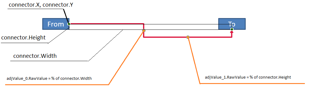
이 예제는 커넥터를 검사하고 가로 및 세로 굽힘 조정을 가져옵니다.
const aspose = { slides: require("aspose.slides.via.java") };
const java = require("java");

const presentation = new aspose.slides.Presentation();
try {
    const slide = presentation.getSlides().get_Item(0);

    const sourceShape = slide.getShapes().addAutoShape(aspose.slides.ShapeType.Rectangle, 100, 100, 60, 25);
    sourceShape.getTextFrame().setText("From");
    const targetShape = slide.getShapes().addAutoShape(aspose.slides.ShapeType.Rectangle, 500, 100, 60, 25);
    targetShape.getTextFrame().setText("To");
    const connector = slide.getShapes().addConnector(aspose.slides.ShapeType.BentConnector4, 20, 20, 400, 300);

    const red = java.getStaticFieldValue("java.awt.Color", "RED");
    const solidFillType = java.newByte(aspose.slides.FillType.Solid);
    const triangleArrowheadStyle = java.newByte(aspose.slides.LineArrowheadStyle.Triangle);
    connector.getLineFormat().setEndArrowheadStyle(triangleArrowheadStyle);
    connector.getLineFormat().getFillFormat().setFillType(solidFillType);
    connector.getLineFormat().getFillFormat().getSolidFillColor().setColor(red);
    connector.getLineFormat().setWidth(3);
    connector.setStartShapeConnectedTo(sourceShape);
    connector.setStartShapeConnectionSiteIndex(3);
    connector.setEndShapeConnectedTo(targetShape);
    connector.setEndShapeConnectionSiteIndex(2);

    for (let adjustmentIndex = 0; adjustmentIndex < connector.getAdjustments().size(); adjustmentIndex++) {
        const adjustment = connector.getAdjustments().get_Item(adjustmentIndex);
        console.log(`${adjustment.getName()}: ${adjustment.getType()}, raw value = ${adjustment.getRawValue()}`);
    }
} finally {
    presentation.dispose();
}
두 굽힘을 모두 변경하려면 각 예상 유형을 찾은 후 값을 수정하십시오.
const aspose = { slides: require("aspose.slides.via.java") };

const presentation = new aspose.slides.Presentation();
try {
    const slide = presentation.getSlides().get_Item(0);

    const sourceShape = slide.getShapes().addAutoShape(aspose.slides.ShapeType.Rectangle, 100, 100, 60, 25);
    const targetShape = slide.getShapes().addAutoShape(aspose.slides.ShapeType.Rectangle, 500, 100, 60, 25);
    const connector = slide.getShapes().addConnector(aspose.slides.ShapeType.BentConnector4, 20, 20, 400, 300);
    connector.setStartShapeConnectedTo(sourceShape);
    connector.setStartShapeConnectionSiteIndex(3);
    connector.setEndShapeConnectedTo(targetShape);
    connector.setEndShapeConnectionSiteIndex(2);

    let horizontalBend = null;
    let verticalBend = null;
    for (let adjustmentIndex = 0; adjustmentIndex < connector.getAdjustments().size(); adjustmentIndex++) {
        const adjustment = connector.getAdjustments().get_Item(adjustmentIndex);
        if (adjustment.getType() === aspose.slides.ShapeAdjustmentType.ConnectorBendPositionX) {
            horizontalBend = adjustment;
        } else if (adjustment.getType() === aspose.slides.ShapeAdjustmentType.ConnectorBendPositionY) {
            verticalBend = adjustment;
        }
    }

    if (horizontalBend === null || verticalBend === null) {
        console.log("The connector does not expose the expected bend adjustments.");
    } else {
        horizontalBend.setRawValue(horizontalBend.getRawValue() + 20000);
        verticalBend.setRawValue(verticalBend.getRawValue() + 200000);
        presentation.save("connector-adjusted.pptx", aspose.slides.SaveFormat.Pptx);
    }
} finally {
    presentation.dispose();
}
그 결과 가로와 세로 세그먼트가 이동한 커넥터가 나타납니다.

의미 유형을 알게 되면 해당 값을 커넥터 프레임 좌표로 변환할 수 있습니다. 이 예제는 두 굽힘 조정이 제어하는 세로 세그먼트 위에 얇은 사각형을 그립니다.
const aspose = { slides: require("aspose.slides.via.java") };
const java = require("java");

const presentation = new aspose.slides.Presentation();
try {
    const slide = presentation.getSlides().get_Item(0);

    const sourceShape = slide.getShapes().addAutoShape(aspose.slides.ShapeType.Rectangle, 100, 100, 60, 25);
    const targetShape = slide.getShapes().addAutoShape(aspose.slides.ShapeType.Rectangle, 500, 100, 60, 25);
    const connector = slide.getShapes().addConnector(aspose.slides.ShapeType.BentConnector4, 20, 20, 400, 300);
    connector.setStartShapeConnectedTo(sourceShape);
    connector.setStartShapeConnectionSiteIndex(3);
    connector.setEndShapeConnectedTo(targetShape);
    connector.setEndShapeConnectionSiteIndex(2);

    let horizontalBend = null;
    let verticalBend = null;
    for (let adjustmentIndex = 0; adjustmentIndex < connector.getAdjustments().size(); adjustmentIndex++) {
        const adjustment = connector.getAdjustments().get_Item(adjustmentIndex);
        if (adjustment.getType() === aspose.slides.ShapeAdjustmentType.ConnectorBendPositionX) {
            horizontalBend = adjustment;
        } else if (adjustment.getType() === aspose.slides.ShapeAdjustmentType.ConnectorBendPositionY) {
            verticalBend = adjustment;
        }
    }

    if (horizontalBend === null || verticalBend === null) {
        console.log("The connector does not expose the expected bend adjustments.");
    } else {
        const x = connector.getX() + connector.getWidth() * horizontalBend.getRawValue() / 100000;
        const y = connector.getY();
        const height = connector.getHeight() * verticalBend.getRawValue() / 100000;
        const guideX = java.newFloat(x);
        const guideY = java.newFloat(y);
        const guideWidth = java.newFloat(1);
        const guideHeight = java.newFloat(height);
        slide.getShapes().addAutoShape(aspose.slides.ShapeType.Rectangle, guideX, guideY, guideWidth, guideHeight);
        presentation.save("connector-segment-guide.pptx", aspose.slides.SaveFormat.Pptx);
    }
} finally {
    presentation.dispose();
}
가이드 도형이 계산된 세그먼트를 표시합니다.

회전 또는 뒤집힌 커넥터
같은 커넥터 기하학이 세로로 배치될 경우, Shape.getFrame, ShapeFrame.getFlipH, ShapeFrame.getFlipV 값이 커넥터 프레임 좌표를 슬라이드 좌표로 변환하는 데 영향을 줍니다.
이 예제는 세로 방향 커넥터를 만들고 조정합니다.
const aspose = { slides: require("aspose.slides.via.java") };
const java = require("java");

const presentation = new aspose.slides.Presentation();
try {
    const slide = presentation.getSlides().get_Item(0);

    const sourceShape = slide.getShapes().addAutoShape(aspose.slides.ShapeType.Rectangle, 100, 100, 60, 25);
    sourceShape.getTextFrame().setText("From");
    const targetShape = slide.getShapes().addAutoShape(aspose.slides.ShapeType.Rectangle, 100, 400, 60, 25);
    targetShape.getTextFrame().setText("To 1");
    const connector = slide.getShapes().addConnector(aspose.slides.ShapeType.BentConnector4, 20, 20, 400, 300);

    const connectorColor = java.newInstanceSync("java.awt.Color", 102, 205, 170);
    const solidFillType = java.newByte(aspose.slides.FillType.Solid);
    const triangleArrowheadStyle = java.newByte(aspose.slides.LineArrowheadStyle.Triangle);
    connector.getLineFormat().setEndArrowheadStyle(triangleArrowheadStyle);
    connector.getLineFormat().getFillFormat().setFillType(solidFillType);
    connector.getLineFormat().getFillFormat().getSolidFillColor().setColor(connectorColor);
    connector.getLineFormat().setWidth(3);
    connector.setStartShapeConnectedTo(sourceShape);
    connector.setStartShapeConnectionSiteIndex(2);
    connector.setEndShapeConnectedTo(targetShape);
    connector.setEndShapeConnectionSiteIndex(3);

    for (let adjustmentIndex = 0; adjustmentIndex < connector.getAdjustments().size(); adjustmentIndex++) {
        const adjustment = connector.getAdjustments().get_Item(adjustmentIndex);
        if (adjustment.getType() === aspose.slides.ShapeAdjustmentType.ConnectorBendPositionX) {
            adjustment.setRawValue(adjustment.getRawValue() + 20000);
        } else if (adjustment.getType() === aspose.slides.ShapeAdjustmentType.ConnectorBendPositionY) {
            adjustment.setRawValue(adjustment.getRawValue() + 200000);
        }
    }

    presentation.save("vertical-connector-adjusted.pptx", aspose.slides.SaveFormat.Pptx);
} finally {
    presentation.dispose();
}
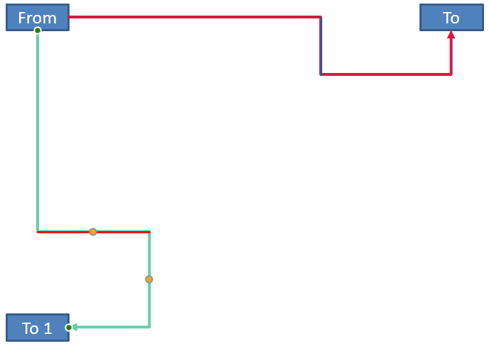
조정된 커넥터가 도형 사이에 세로로 표시됩니다.
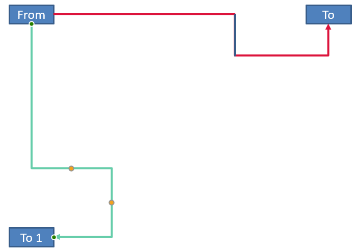
임의의 회전 각도 alpha에 대해 커넥터 프레임 점 (x, y)를 프레임 중심 (x0, y0)을 기준으로 회전하면:
X = (x - x0) * cos(alpha) - (y - y0) * sin(alpha) + x0
Y = (x - x0) * sin(alpha) + (y - y0) * cos(alpha) + y0
다음 코드는 이 예제에서 사용된 90도 방향을 처리하고 해당 커넥터 세그먼트 위에 빨간 가이드를 그립니다.
const aspose = { slides: require("aspose.slides.via.java") };
const java = require("java");

const presentation = new aspose.slides.Presentation();
try {
    const slide = presentation.getSlides().get_Item(0);

    const sourceShape = slide.getShapes().addAutoShape(aspose.slides.ShapeType.Rectangle, 100, 100, 60, 25);
    const targetShape = slide.getShapes().addAutoShape(aspose.slides.ShapeType.Rectangle, 100, 400, 60, 25);
    const connector = slide.getShapes().addConnector(aspose.slides.ShapeType.BentConnector4, 20, 20, 400, 300);
    connector.setStartShapeConnectedTo(sourceShape);
    connector.setStartShapeConnectionSiteIndex(2);
    connector.setEndShapeConnectedTo(targetShape);
    connector.setEndShapeConnectionSiteIndex(3);

    let horizontalBend = null;
    let verticalBend = null;
    for (let adjustmentIndex = 0; adjustmentIndex < connector.getAdjustments().size(); adjustmentIndex++) {
        const adjustment = connector.getAdjustments().get_Item(adjustmentIndex);
        if (adjustment.getType() === aspose.slides.ShapeAdjustmentType.ConnectorBendPositionX) {
            horizontalBend = adjustment;
        } else if (adjustment.getType() === aspose.slides.ShapeAdjustmentType.ConnectorBendPositionY) {
            verticalBend = adjustment;
        }
    }

    if (horizontalBend === null || verticalBend === null) {
        console.log("The connector does not expose the expected bend adjustments.");
    } else {
        horizontalBend.setRawValue(horizontalBend.getRawValue() + 20000);
        verticalBend.setRawValue(verticalBend.getRawValue() + 200000);

        let x = connector.getX();
        let y = connector.getY();
        if (connector.getFrame().getFlipH() === aspose.slides.NullableBool.True) {
            x += connector.getWidth();
        }
        if (connector.getFrame().getFlipV() === aspose.slides.NullableBool.True) {
            y += connector.getHeight();
        }

        x += connector.getWidth() * horizontalBend.getRawValue() / 100000;
        const rotatedX = connector.getFrame().getCenterX() - y + connector.getFrame().getCenterY();
        const rotatedY = x - connector.getFrame().getCenterX() + connector.getFrame().getCenterY();
        const segmentWidth = connector.getHeight() * verticalBend.getRawValue() / 100000;
        const guideX = java.newFloat(rotatedX);
        const guideY = java.newFloat(rotatedY);
        const guideWidth = java.newFloat(segmentWidth);
        const guideHeight = java.newFloat(1);
        const guide = slide.getShapes().addAutoShape(aspose.slides.ShapeType.Rectangle, guideX, guideY, guideWidth, guideHeight);
        const red = java.getStaticFieldValue("java.awt.Color", "RED");
        const solidFillType = java.newByte(aspose.slides.FillType.Solid);
        guide.getLineFormat().getFillFormat().setFillType(solidFillType);
        guide.getLineFormat().getFillFormat().getSolidFillColor().setColor(red);

        presentation.save("rotated-connector-segment-guide.pptx", aspose.slides.SaveFormat.Pptx);
    }
} finally {
    presentation.dispose();
}
좌표 변환 후 빨간 가이드가 계산된 세그먼트를 표시합니다.
이 공식은 예제에 사용된 프리셋을 설명할 뿐이며, 보편적인 커넥터 모델을 정의하지 않습니다. 다른 프리셋에 동일한 계산을 적용하기 전에 조정 유형, 프레임 방향 및 값 범위를 검증하십시오.
커넥터 방향 각도 찾기
직선 커넥터의 방향은 가로·세로 길이와 가로·세로 뒤집기를 적용해 계산할 수 있습니다. 다음 예제는 슬라이드 좌표계에서 양의 가로 축을 기준으로 시계 방향 각도를 보고합니다.
const aspose = { slides: require("aspose.slides.via.java") };

const presentation = new aspose.slides.Presentation();
try {
    const slide = presentation.getSlides().get_Item(0);
    const connector = slide.getShapes().addConnector(aspose.slides.ShapeType.StraightConnector1, 100, 100, 200, 100);

    const flipH = connector.getFrame().getFlipH() === aspose.slides.NullableBool.True;
    const flipV = connector.getFrame().getFlipV() === aspose.slides.NullableBool.True;
    const deltaX = connector.getWidth() * (flipH ? -1 : 1);
    const deltaY = connector.getHeight() * (flipV ? -1 : 1);
    let angle = Math.atan2(deltaY, deltaX) * 180.0 / Math.PI;

    if (angle < 0) {
        angle += 360;
    }

    console.log(`Connector direction: ${angle.toFixed(2)} degrees`);
} finally {
    presentation.dispose();
}
FAQ
커넥터가 도형에 연결될 수 있는지 어떻게 확인합니까?
도형의 getConnectionSiteCount 값을 확인하십시오. 양수이면 도형이 연결 지점을 노출한다는 의미입니다. 선택한 사이트 인덱스를 커넥터 양쪽 끝에 할당하기 전에 반드시 검증하십시오.
컬렉션 인덱스로 커넥터 조정을 식별할 수 있나요?
인덱스는 알려진 커넥터 프리셋과 컬렉션 레이아웃에서만 의미가 있습니다. 값을 수정하기 전에 AdjustValue.getType을 확인하고, 동일한 의미 유형이 여러 번 나타날 경우 AdjustValue.getName을 추가 정보로 활용하십시오.
연결된 도형이 삭제되면 어떻게 됩니까?
해당 커넥터 끝이 분리됩니다. 커넥터는 슬라이드에 남아 자유 선으로 위치를 조정하거나 다른 도형에 다시 연결하거나 삭제할 수 있습니다.
슬라이드 복사 시 커넥터 바인딩이 유지되나요?
연결된 도형이 슬라이드와 함께 복사되면 바인딩이 일반적으로 유지됩니다. 커넥터만 복사되고 대상 도형 중 하나가 없을 경우, 영향을 받은 끝을 다시 연결해야 합니다.