
.NET에서 프레젠테이션의 연결선 관리
Overview
연결선은 두 도형이 움직이더라도 두 도형에 부착된 상태를 유지할 수 있는 선입니다. 끝부분은 PowerPoint에서 녹색 점으로 표시되는 연결 지점에 연결됩니다. 일부 굽은 연결선 및 곡선 연결선은 주황색 점으로 표시되는 조정점을 제공하여 개별 연결선 세그먼트의 위치를 제어합니다.
Aspose.Slides는 연결선을 IConnector 인터페이스를 통해 나타냅니다. 연결선을 만들고, 끝을 도형에 연결하고, 연결 지점을 선택하고, 경로를 다시 잡으며, 조정점이 있는 연결선의 기하학을 수정할 수 있습니다.
Connector Types
ShapeType 열거형에는 직선, 굽은 및 곡선 연결선 프리셋이 포함됩니다. 다음 표는 사용 가능한 연결선 기하학과 각 프리셋이 정의하는 조정점 수를 보여 줍니다.
| Connector | Image | Number of adjustment points |
|---|---|---|
ShapeType.Line |
 |
0 |
ShapeType.StraightConnector1 |
 |
0 |
ShapeType.BentConnector2 |
 |
0 |
ShapeType.BentConnector3 |
 |
1 |
ShapeType.BentConnector4 |
 |
2 |
ShapeType.BentConnector5 |
 |
3 |
ShapeType.CurvedConnector2 |
 |
0 |
ShapeType.CurvedConnector3 |
 |
1 |
ShapeType.CurvedConnector4 |
 |
2 |
ShapeType.CurvedConnector5 |
 |
3 |
조정점의 수와 의미는 선택한 연결선 프리셋에 따라 달라집니다. 두 가지 다른 연결선 유형이 동일한 컬렉션 레이아웃을 제공한다고 가정하지 마세요.
Connect Two Shapes
IShapeCollection.AddConnector를 사용하여 연결선을 추가하고, 해당 연결선의 StartShapeConnectedTo 및 EndShapeConnectedTo 속성을 지정합니다. 두 끝이 모두 연결된 후, IConnector.Reroute를 호출하면 도형 사이의 짧은 경로가 선택됩니다.
다음 예시는 타원과 사각형을 굽은 연결선으로 연결합니다.
using Aspose.Slides;
using Aspose.Slides.Export;

using var presentation = new Presentation();
var slide = presentation.Slides[0];

var ellipse = slide.Shapes.AddAutoShape(ShapeType.Ellipse, 40, 80, 120, 80);
var rectangle = slide.Shapes.AddAutoShape(ShapeType.Rectangle, 320, 240, 140, 80);
var connector = slide.Shapes.AddConnector(ShapeType.BentConnector2, 0, 0, 10, 10);

connector.StartShapeConnectedTo = ellipse;
connector.EndShapeConnectedTo = rectangle;
connector.Reroute();

presentation.Save("connected-shapes.pptx", SaveFormat.Pptx);
Warning
Reroute를 호출하면 StartShapeConnectionSiteIndex 및 EndShapeConnectionSiteIndex 값이 변경될 수 있습니다. 해당 사이트를 고정해야 하는 경우, 경로를 다시 잡은 후에 특정 연결 지점을 다시 할당하세요.
Choose a Connection Site
각 연결 가능한 도형은 ConnectionSiteCount을 통해 사이트 수를 보고합니다. 연결선 끝에 할당하기 전에 선호하는 0 기반 사이트 인덱스를 검증하세요; 사이트 수는 도형의 기하학에 따라 다릅니다.
다음 예시는 해당 사이트가 존재할 경우 타원의 특정 사이트에 연결선을 연결합니다.
using System;
using Aspose.Slides;
using Aspose.Slides.Export;

using var presentation = new Presentation();
var slide = presentation.Slides[0];

var ellipse = slide.Shapes.AddAutoShape(ShapeType.Ellipse, 40, 80, 120, 80);
var rectangle = slide.Shapes.AddAutoShape(ShapeType.Rectangle, 320, 240, 140, 80);
var connector = slide.Shapes.AddConnector(ShapeType.BentConnector3, 0, 0, 10, 10);

connector.StartShapeConnectedTo = ellipse;
connector.EndShapeConnectedTo = rectangle;

uint preferredSiteIndex = 2;
if (preferredSiteIndex < ellipse.ConnectionSiteCount)
{
    connector.StartShapeConnectionSiteIndex = preferredSiteIndex;
}
else
{
    Console.WriteLine($"The ellipse has only {ellipse.ConnectionSiteCount} connection sites.");
}

presentation.Save("specific-connection-site.pptx", SaveFormat.Pptx);
Adjust a Connector Point
조정점을 가진 연결선은 IGeometryShape.Adjustments를 통해 노출됩니다. 각 IAdjustValue를 검사하고, Type을 확인한 후 RawValue를 변경하세요. 프리셋 도형 조정 식별에 대한 일반 규칙은 Shape Manipulation에 설명되어 있습니다.
연결선 조정의 수, 순서, 의미 및 유효값 범위는 연결선 프리셋에 따라 달라집니다. Type 속성은 읽기 전용이며, 조정값은 쓰기가 가능합니다. 동일한 의미 유형에 대해 여러 조정이 존재하는 경우, 읽기 전용 Name 속성이 추가 식별 정보를 제공합니다.
Route Around an Obstacle
다음 레이아웃에서 두 도형 사이의 BentConnector5 연결선이 세 번째 도형을 통과합니다.

이 코드는 방해되는 연결선을 생성합니다.
using System.Drawing;
using Aspose.Slides;
using Aspose.Slides.Export;

using var presentation = new Presentation();
var slide = presentation.Slides[0];

slide.Shapes.AddAutoShape(ShapeType.Rectangle, 300, 150, 150, 75);
var sourceShape = slide.Shapes.AddAutoShape(ShapeType.Rectangle, 500, 400, 100, 50);
var targetShape = slide.Shapes.AddAutoShape(ShapeType.Rectangle, 100, 100, 70, 30);
var connector = slide.Shapes.AddConnector(ShapeType.BentConnector5, 20, 20, 400, 300);

connector.LineFormat.EndArrowheadStyle = LineArrowheadStyle.Triangle;
connector.LineFormat.FillFormat.FillType = FillType.Solid;
connector.LineFormat.FillFormat.SolidFillColor.Color = Color.Black;
connector.StartShapeConnectedTo = sourceShape;
connector.EndShapeConnectedTo = targetShape;
connector.StartShapeConnectionSiteIndex = 2;

presentation.Save("connector-obstruction.pptx", SaveFormat.Pptx);
세로 굽힘을 이동하면 경로가 바뀌어 연결선이 장애물을 우회합니다.

컬렉션 인덱스 1이 항상 세로 굽힘을 나타낸다고 가정하는 대신, 이 예시는 ConnectorBendPositionY를 찾아 기대되는 의미 유형이 존재할 때만 변경합니다.
using System;
using System.Drawing;
using Aspose.Slides;
using Aspose.Slides.Export;

using var presentation = new Presentation();
var slide = presentation.Slides[0];

slide.Shapes.AddAutoShape(ShapeType.Rectangle, 300, 150, 150, 75);
var sourceShape = slide.Shapes.AddAutoShape(ShapeType.Rectangle, 500, 400, 100, 50);
var targetShape = slide.Shapes.AddAutoShape(ShapeType.Rectangle, 100, 100, 70, 30);
var connector = slide.Shapes.AddConnector(ShapeType.BentConnector5, 20, 20, 400, 300);

connector.LineFormat.EndArrowheadStyle = LineArrowheadStyle.Triangle;
connector.LineFormat.FillFormat.FillType = FillType.Solid;
connector.LineFormat.FillFormat.SolidFillColor.Color = Color.Black;
connector.StartShapeConnectedTo = sourceShape;
connector.EndShapeConnectedTo = targetShape;
connector.StartShapeConnectionSiteIndex = 2;

IAdjustValue? verticalBend = null;
for (var adjustmentIndex = 0; adjustmentIndex < connector.Adjustments.Count; adjustmentIndex++)
{
    var adjustment = connector.Adjustments[adjustmentIndex];
    Console.WriteLine($"{adjustment.Name}: {adjustment.Type}, raw value = {adjustment.RawValue}");
    if (adjustment.Type == ShapeAdjustmentType.ConnectorBendPositionY)
    {
        verticalBend = adjustment;
        break;
    }
}

if (verticalBend is null)
{
    Console.WriteLine("The connector does not expose a vertical bend adjustment.");
}
else
{
    verticalBend.RawValue = 60000;
    presentation.Save("connector-obstruction-fixed.pptx", SaveFormat.Pptx);
}
BentConnector5에는 두 개의 ConnectorBendPositionX 조정과 하나의 ConnectorBendPositionY 조정이 있습니다. 필요한 유형이 여러 번 발생하면, Name과 해당 프리셋의 알려진 기하학을 확인한 후 선택하세요. 조정이 ShapeAdjustmentType.Custom을 반환하면 의미와 범위는 프리셋별이며, 계약이 명확해질 때까지 변경하지 마세요.
Relate Adjustment Values to Connector Geometry
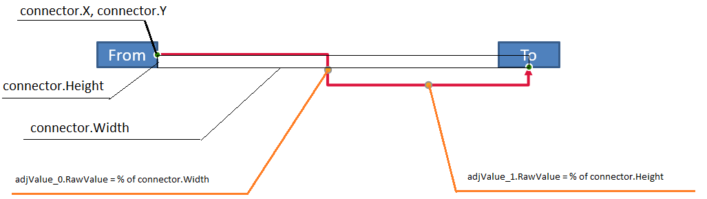
굽은 연결선의 경우, 조정값을 사용하여 개별 세그먼트 위치를 추정할 수 있습니다. 이러한 계산은 연결선 프리셋에 특화됩니다.
BentConnector4는 일반적으로 하나의ConnectorBendPositionX와 하나의ConnectorBendPositionY조정을 노출합니다.- 이러한 굽힘 위치에 대해
RawValue / 100000f는 아래 예제에서 사용되는 연결선 프레임 너비 또는 높이의 비율을 생성합니다. - 연결선 프레임은 회전하거나 뒤집을 수 있으므로, 프레임 좌표를 슬라이드 좌표와 비교하기 전에 변환해야 합니다.
다음 예제는 먼저 Type을 사용해 조정을 식별합니다. 컬렉션 인덱스를 이식 가능한 식별자로 취급하지 않습니다.
Unrotated Connector
초기 레이아웃에는 BentConnector4로 연결된 두 텍스트 도형이 있습니다.
이 예시는 연결선을 검사하고 수평 및 수직 굽힘 조정을 가져옵니다.
using System;
using System.Drawing;
using Aspose.Slides;

using var presentation = new Presentation();
var slide = presentation.Slides[0];

var sourceShape = slide.Shapes.AddAutoShape(ShapeType.Rectangle, 100, 100, 60, 25);
sourceShape.TextFrame.Text = "From";
var targetShape = slide.Shapes.AddAutoShape(ShapeType.Rectangle, 500, 100, 60, 25);
targetShape.TextFrame.Text = "To";
var connector = slide.Shapes.AddConnector(ShapeType.BentConnector4, 20, 20, 400, 300);

connector.LineFormat.EndArrowheadStyle = LineArrowheadStyle.Triangle;
connector.LineFormat.FillFormat.FillType = FillType.Solid;
connector.LineFormat.FillFormat.SolidFillColor.Color = Color.Crimson;
connector.LineFormat.Width = 3;
connector.StartShapeConnectedTo = sourceShape;
connector.StartShapeConnectionSiteIndex = 3;
connector.EndShapeConnectedTo = targetShape;
connector.EndShapeConnectionSiteIndex = 2;

for (var adjustmentIndex = 0; adjustmentIndex < connector.Adjustments.Count; adjustmentIndex++)
{
    var adjustment = connector.Adjustments[adjustmentIndex];
    Console.WriteLine($"{adjustment.Name}: {adjustment.Type}, raw value = {adjustment.RawValue}");
}
두 굽힘을 모두 변경하려면 각 기대 유형을 찾아 두 값이 모두 발견된 후에만 수정합니다.
using System;
using Aspose.Slides;
using Aspose.Slides.Export;

using var presentation = new Presentation();
var slide = presentation.Slides[0];

var sourceShape = slide.Shapes.AddAutoShape(ShapeType.Rectangle, 100, 100, 60, 25);
var targetShape = slide.Shapes.AddAutoShape(ShapeType.Rectangle, 500, 100, 60, 25);
var connector = slide.Shapes.AddConnector(ShapeType.BentConnector4, 20, 20, 400, 300);
connector.StartShapeConnectedTo = sourceShape;
connector.StartShapeConnectionSiteIndex = 3;
connector.EndShapeConnectedTo = targetShape;
connector.EndShapeConnectionSiteIndex = 2;

IAdjustValue? horizontalBend = null;
IAdjustValue? verticalBend = null;
for (var adjustmentIndex = 0; adjustmentIndex < connector.Adjustments.Count; adjustmentIndex++)
{
    var adjustment = connector.Adjustments[adjustmentIndex];
    if (adjustment.Type == ShapeAdjustmentType.ConnectorBendPositionX)
    {
        horizontalBend = adjustment;
    }
    else if (adjustment.Type == ShapeAdjustmentType.ConnectorBendPositionY)
    {
        verticalBend = adjustment;
    }
}

if (horizontalBend is null || verticalBend is null)
{
    Console.WriteLine("The connector does not expose the expected bend adjustments.");
}
else
{
    horizontalBend.RawValue += 20000;
    verticalBend.RawValue += 200000;
    presentation.Save("connector-adjusted.pptx", SaveFormat.Pptx);
}
그 결과 수평 및 수직 세그먼트가 이동한 연결선이 나타납니다.

의미 유형이 확인되면 값을 연결선 프레임 좌표로 변환할 수 있습니다. 이 예시는 두 굽힘 조정이 제어하는 수직 세그먼트 위에 얇은 사각형을 그립니다.
using System;
using Aspose.Slides;
using Aspose.Slides.Export;

using var presentation = new Presentation();
var slide = presentation.Slides[0];

var sourceShape = slide.Shapes.AddAutoShape(ShapeType.Rectangle, 100, 100, 60, 25);
var targetShape = slide.Shapes.AddAutoShape(ShapeType.Rectangle, 500, 100, 60, 25);
var connector = slide.Shapes.AddConnector(ShapeType.BentConnector4, 20, 20, 400, 300);
connector.StartShapeConnectedTo = sourceShape;
connector.StartShapeConnectionSiteIndex = 3;
connector.EndShapeConnectedTo = targetShape;
connector.EndShapeConnectionSiteIndex = 2;

IAdjustValue? horizontalBend = null;
IAdjustValue? verticalBend = null;
for (var adjustmentIndex = 0; adjustmentIndex < connector.Adjustments.Count; adjustmentIndex++)
{
    var adjustment = connector.Adjustments[adjustmentIndex];
    if (adjustment.Type == ShapeAdjustmentType.ConnectorBendPositionX)
    {
        horizontalBend = adjustment;
    }
    else if (adjustment.Type == ShapeAdjustmentType.ConnectorBendPositionY)
    {
        verticalBend = adjustment;
    }
}

if (horizontalBend is null || verticalBend is null)
{
    Console.WriteLine("The connector does not expose the expected bend adjustments.");
}
else
{
    var x = connector.X + connector.Width * horizontalBend.RawValue / 100000f;
    var y = connector.Y;
    var height = connector.Height * verticalBend.RawValue / 100000f;
    slide.Shapes.AddAutoShape(ShapeType.Rectangle, x, y, 1, height);
    presentation.Save("connector-segment-guide.pptx", SaveFormat.Pptx);
}
가이드 도형은 계산된 세그먼트를 표시합니다.

Rotated or Flipped Connector
동일한 연결선 기하학이 수직으로 배치될 때, Frame, FlipH, FlipV 값이 연결선 프레임 좌표를 슬라이드 좌표로 변환하는 방식에 영향을 줍니다.
이 예시는 수직으로 배치된 연결선을 생성하고 조정합니다.
using System;
using System.Drawing;
using Aspose.Slides;
using Aspose.Slides.Export;

using var presentation = new Presentation();
var slide = presentation.Slides[0];

var sourceShape = slide.Shapes.AddAutoShape(ShapeType.Rectangle, 100, 100, 60, 25);
sourceShape.TextFrame.Text = "From";
var targetShape = slide.Shapes.AddAutoShape(ShapeType.Rectangle, 100, 400, 60, 25);
targetShape.TextFrame.Text = "To 1";
var connector = slide.Shapes.AddConnector(ShapeType.BentConnector4, 20, 20, 400, 300);

connector.LineFormat.EndArrowheadStyle = LineArrowheadStyle.Triangle;
connector.LineFormat.FillFormat.FillType = FillType.Solid;
connector.LineFormat.FillFormat.SolidFillColor.Color = Color.MediumAquamarine;
connector.LineFormat.Width = 3;
connector.StartShapeConnectedTo = sourceShape;
connector.StartShapeConnectionSiteIndex = 2;
connector.EndShapeConnectedTo = targetShape;
connector.EndShapeConnectionSiteIndex = 3;

for (var adjustmentIndex = 0; adjustmentIndex < connector.Adjustments.Count; adjustmentIndex++)
{
    var adjustment = connector.Adjustments[adjustmentIndex];
    if (adjustment.Type == ShapeAdjustmentType.ConnectorBendPositionX)
    {
        adjustment.RawValue += 20000;
    }
    else if (adjustment.Type == ShapeAdjustmentType.ConnectorBendPositionY)
    {
        adjustment.RawValue += 200000;
    }
}

presentation.Save("vertical-connector-adjusted.pptx", SaveFormat.Pptx);
조정된 연결선은 도형 사이에 수직으로 표시됩니다.

임의의 회전 각도 alpha에 대해, 연결선 프레임 점 (x, y)를 프레임 중심 (x0, y0) 주위로 회전하면:
X = (x - x0) * cos(alpha) - (y - y0) * sin(alpha) + x0
Y = (x - x0) * sin(alpha) + (y - y0) * cos(alpha) + y0
다음 코드는 이 예제에서 사용된 90도 방향을 처리하고, 해당 연결선 세그먼트 위에 빨간색 가이드를 그립니다.
using System;
using System.Drawing;
using Aspose.Slides;
using Aspose.Slides.Export;

using var presentation = new Presentation();
var slide = presentation.Slides[0];

var sourceShape = slide.Shapes.AddAutoShape(ShapeType.Rectangle, 100, 100, 60, 25);
var targetShape = slide.Shapes.AddAutoShape(ShapeType.Rectangle, 100, 400, 60, 25);
var connector = slide.Shapes.AddConnector(ShapeType.BentConnector4, 20, 20, 400, 300);
connector.StartShapeConnectedTo = sourceShape;
connector.StartShapeConnectionSiteIndex = 2;
connector.EndShapeConnectedTo = targetShape;
connector.EndShapeConnectionSiteIndex = 3;

IAdjustValue? horizontalBend = null;
IAdjustValue? verticalBend = null;
for (var adjustmentIndex = 0; adjustmentIndex < connector.Adjustments.Count; adjustmentIndex++)
{
    var adjustment = connector.Adjustments[adjustmentIndex];
    if (adjustment.Type == ShapeAdjustmentType.ConnectorBendPositionX)
    {
        horizontalBend = adjustment;
    }
    else if (adjustment.Type == ShapeAdjustmentType.ConnectorBendPositionY)
    {
        verticalBend = adjustment;
    }
}

if (horizontalBend is null || verticalBend is null)
{
    Console.WriteLine("The connector does not expose the expected bend adjustments.");
}
else
{
    horizontalBend.RawValue += 20000;
    verticalBend.RawValue += 200000;

    var x = connector.X;
    var y = connector.Y;
    if (connector.Frame.FlipH == NullableBool.True)
    {
        x += connector.Width;
    }
    if (connector.Frame.FlipV == NullableBool.True)
    {
        y += connector.Height;
    }

    x += connector.Width * horizontalBend.RawValue / 100000f;
    var rotatedX = connector.Frame.CenterX - y + connector.Frame.CenterY;
    var rotatedY = x - connector.Frame.CenterX + connector.Frame.CenterY;
    var segmentWidth = connector.Height * verticalBend.RawValue / 100000f;
    var guide = slide.Shapes.AddAutoShape(ShapeType.Rectangle, rotatedX, rotatedY, segmentWidth, 1);
    guide.LineFormat.FillFormat.FillType = FillType.Solid;
    guide.LineFormat.FillFormat.SolidFillColor.Color = Color.Red;

    presentation.Save("rotated-connector-segment-guide.pptx", SaveFormat.Pptx);
}
좌표 변환 후 빨간색 가이드는 계산된 세그먼트를 표시합니다.

이 수식은 예제에 사용된 프리셋을 설명한 것이며 보편적인 연결선 모델을 의미하지 않습니다. 다른 프리셋에 동일한 계산을 적용하기 전에 조정 유형, 프레임 방향 및 값 범위를 검증하세요.
Find a Connector Direction Angle
직선 연결선의 방향은 너비와 높이, 그리고 수평·수직 뒤집기를 적용하여 계산할 수 있습니다. 다음 예제는 슬라이드 좌표계에서 양의 수평 축을 기준으로 시계 방향 각도를 보고합니다.
using System;
using Aspose.Slides;

using var presentation = new Presentation();
var slide = presentation.Slides[0];
var connector = slide.Shapes.AddConnector(ShapeType.StraightConnector1, 100, 100, 200, 100);

var flipH = connector.Frame.FlipH == NullableBool.True;
var flipV = connector.Frame.FlipV == NullableBool.True;
var deltaX = connector.Width * (flipH ? -1 : 1);
var deltaY = connector.Height * (flipV ? -1 : 1);
var angle = Math.Atan2(deltaY, deltaX) * 180.0 / Math.PI;

if (angle < 0)
{
    angle += 360;
}

Console.WriteLine($"Connector direction: {angle:F2} degrees");
FAQ
How can I tell whether a connector can attach to a shape?
도형의 ConnectionSiteCount를 확인하세요. 양수 값은 도형이 연결 지점을 제공한다는 의미입니다. 연결선 끝에 할당하기 전에 선택한 사이트 인덱스를 검증하세요.
Can I identify a connector adjustment by its collection index?
인덱스는 알려진 연결선 프리셋 및 컬렉션 레이아웃에 대해서만 의미가 있습니다. 값을 수정하기 전에 IAdjustValue.Type을 확인하고, 동일한 의미 유형이 여러 번 나타날 경우 IAdjustValue.Name을 추가 정보로 사용하세요.
What happens when a connected shape is deleted?
해당 연결선 끝은 분리됩니다. 연결선은 슬라이드에 남아 자유선으로 유지되거나 삭제되거나 다른 도형에 다시 연결될 수 있습니다.
Are connector bindings preserved when a slide is copied?
연결된 도형과 함께 슬라이드가 복사되면 일반적으로 바인딩이 유지됩니다. 연결선만 복사되고 대상 도형 중 하나가 없을 경우, 영향을 받은 끝을 다시 연결해야 합니다.