
在 Java 簡報中管理連接線
概觀
連接線是一條在任一形狀移動時仍能保持連接兩個形狀的線。其兩端會附著在連接點上,在 PowerPoint 中以綠點表示。某些彎曲與曲線連接線還會顯示調整點,以橙點表示,這些點可控制個別連接線段的位置。
Aspose.Slides 透過 IConnector 介面來表示連接線。您可以建立連接線、將其兩端附著到形狀、選擇連接點、重新路由,並修改具有調整點的連接線幾何形狀。
連接線類型
ShapeType 類別包含直線、彎曲與曲線連接線預設。下表顯示可用的連接線幾何形狀以及每個預設所定義的調整點數量。
| 連接線 | 圖片 | 調整點數量 |
|---|---|---|
ShapeType.Line |
 |
0 |
ShapeType.StraightConnector1 |
 |
0 |
ShapeType.BentConnector2 |
 |
0 |
ShapeType.BentConnector3 |
 |
1 |
ShapeType.BentConnector4 |
 |
2 |
ShapeType.BentConnector5 |
 |
3 |
ShapeType.CurvedConnector2 |
 |
0 |
ShapeType.CurvedConnector3 |
 |
1 |
ShapeType.CurvedConnector4 |
 |
2 |
ShapeType.CurvedConnector5 |
 |
3 |
調整點的數量與意義屬於所選的連接線預設。不要假設兩種不同的連接線類型會公開相同的集合佈局。
連接兩個形狀
使用 IShapeCollection.addConnector 來新增連接線,並使用 IConnector.setStartShapeConnectedTo 與 IConnector.setEndShapeConnectedTo 來附著兩端。兩端皆附著後,呼叫 IConnector.reroute 會在形狀之間選擇最短路徑。
以下範例使用彎曲連接線連接橢圓與矩形:
import com.aspose.slides.*;

Presentation presentation = new Presentation();
try {
    ISlide slide = presentation.getSlides().get_Item(0);

    IAutoShape ellipse = slide.getShapes().addAutoShape(ShapeType.Ellipse, 40, 80, 120, 80);
    IAutoShape rectangle = slide.getShapes().addAutoShape(ShapeType.Rectangle, 320, 240, 140, 80);
    IConnector connector = slide.getShapes().addConnector(ShapeType.BentConnector2, 0, 0, 10, 10);

    connector.setStartShapeConnectedTo(ellipse);
    connector.setEndShapeConnectedTo(rectangle);
    connector.reroute();

    presentation.save("connected-shapes.pptx", SaveFormat.Pptx);
} finally {
    presentation.dispose();
}
警告
呼叫reroute 可能會變更 setStartShapeConnectionSiteIndex 與 setEndShapeConnectionSiteIndex 的值。若這些站點必須保持固定,請在重新路由後再指定具體的連接點。
選擇連接點
每個可連接的形狀會透過 IShape.getConnectionSiteCount 回報其連接點數量。將首選的零基索引指派給連接線端之前,請先驗證索引是否合法;不同形狀的站點數量會因幾何形狀而異。
此範例在橢圓上有特定站點時將連接線附著到該站點:
import com.aspose.slides.*;

Presentation presentation = new Presentation();
try {
    ISlide slide = presentation.getSlides().get_Item(0);

    IAutoShape ellipse = slide.getShapes().addAutoShape(ShapeType.Ellipse, 40, 80, 120, 80);
    IAutoShape rectangle = slide.getShapes().addAutoShape(ShapeType.Rectangle, 320, 240, 140, 80);
    IConnector connector = slide.getShapes().addConnector(ShapeType.BentConnector3, 0, 0, 10, 10);

    connector.setStartShapeConnectedTo(ellipse);
    connector.setEndShapeConnectedTo(rectangle);

    long preferredSiteIndex = 2;
    if (preferredSiteIndex < ellipse.getConnectionSiteCount()) {
        connector.setStartShapeConnectionSiteIndex(preferredSiteIndex);
    } else {
        System.out.println("The ellipse has only " + ellipse.getConnectionSiteCount() + " connection sites.");
    }

    presentation.save("specific-connection-site.pptx", SaveFormat.Pptx);
} finally {
    presentation.dispose();
}
調整連接線點
具有調整點的連接線會透過 IGeometryShape.getAdjustments 暴露這些點。檢查每個 IAdjustValue 並在使用 setRawValue 變更之前,先檢查其 getType 值。關於辨識預設形狀調整的通用規則,請參考 Shape Manipulation。
調整點的數量、順序、意義與有效值範圍取決於連接線預設。調整類型是唯讀的,調整值則可寫。唯讀的 getName 方法在同一語意類型出現多次時提供額外辨識資訊。
繞過障礙物的路徑
下圖中,BentConnector5 連接線在兩個形狀之間穿過第三個形狀:
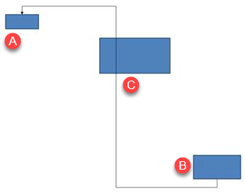
以下程式碼建立了受阻的連接線:
import com.aspose.slides.*;
import java.awt.Color;

Presentation presentation = new Presentation();
try {
    ISlide slide = presentation.getSlides().get_Item(0);

    slide.getShapes().addAutoShape(ShapeType.Rectangle, 300, 150, 150, 75);
    IAutoShape sourceShape = slide.getShapes().addAutoShape(ShapeType.Rectangle, 500, 400, 100, 50);
    IAutoShape targetShape = slide.getShapes().addAutoShape(ShapeType.Rectangle, 100, 100, 70, 30);
    IConnector connector = slide.getShapes().addConnector(ShapeType.BentConnector5, 20, 20, 400, 300);

    connector.getLineFormat().setEndArrowheadStyle(LineArrowheadStyle.Triangle);
    connector.getLineFormat().getFillFormat().setFillType(FillType.Solid);
    connector.getLineFormat().getFillFormat().getSolidFillColor().setColor(Color.BLACK);
    connector.setStartShapeConnectedTo(sourceShape);
    connector.setEndShapeConnectedTo(targetShape);
    connector.setStartShapeConnectionSiteIndex(2);

    presentation.save("connector-obstruction.pptx", SaveFormat.Pptx);
} finally {
    presentation.dispose();
}
移動垂直彎曲點會改變路徑,使連接線繞過障礙物:
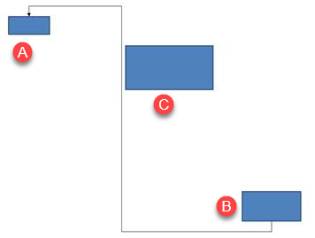
此範例不假設集合索引 1 永遠代表垂直彎曲,而是搜尋 ConnectorBendPositionY,並僅在語意類型符合時才變更:
import com.aspose.slides.*;
import java.awt.Color;

Presentation presentation = new Presentation();
try {
    ISlide slide = presentation.getSlides().get_Item(0);

    slide.getShapes().addAutoShape(ShapeType.Rectangle, 300, 150, 150, 75);
    IAutoShape sourceShape = slide.getShapes().addAutoShape(ShapeType.Rectangle, 500, 400, 100, 50);
    IAutoShape targetShape = slide.getShapes().addAutoShape(ShapeType.Rectangle, 100, 100, 70, 30);
    IConnector connector = slide.getShapes().addConnector(ShapeType.BentConnector5, 20, 20, 400, 300);

    connector.getLineFormat().setEndArrowheadStyle(LineArrowheadStyle.Triangle);
    connector.getLineFormat().getFillFormat().setFillType(FillType.Solid);
    connector.getLineFormat().getFillFormat().getSolidFillColor().setColor(Color.BLACK);
    connector.setStartShapeConnectedTo(sourceShape);
    connector.setEndShapeConnectedTo(targetShape);
    connector.setStartShapeConnectionSiteIndex(2);

    IAdjustValue verticalBend = null;
    for (int adjustmentIndex = 0; adjustmentIndex < connector.getAdjustments().size(); adjustmentIndex++) {
        IAdjustValue adjustment = connector.getAdjustments().get_Item(adjustmentIndex);
        System.out.println(adjustment.getName() + ": " + adjustment.getType() + ", raw value = " + adjustment.getRawValue());
        if (adjustment.getType() == ShapeAdjustmentType.ConnectorBendPositionY) {
            verticalBend = adjustment;
            break;
        }
    }

    if (verticalBend == null) {
        System.out.println("The connector does not expose a vertical bend adjustment.");
    } else {
        verticalBend.setRawValue(60000);
        presentation.save("connector-obstruction-fixed.pptx", SaveFormat.Pptx);
    }
} finally {
    presentation.dispose();
}
BentConnector5 具有兩個 ConnectorBendPositionX 調整與一個 ConnectorBendPositionY 調整。若需要的類型出現多次,請檢查 getName 與該預設的已知幾何形狀後再選擇。若調整回傳 ShapeAdjustmentType.Custom,視為特定預設的語意,除非已瞭解其合約,否則不要變更。
將調整值對應至連接線幾何形狀
對於彎曲連接線,調整值可用來估算各段的座標。這些計算僅適用於特定連接線預設:
BentConnector4通常會公開一個ConnectorBendPositionX與一個ConnectorBendPositionY調整。- 對於這些彎曲位置,將
getRawValue回傳的值除以100000f,即可得到相對於連接線框寬度或高度的比例,以下範例皆採此方式。 - 連接線框可能會旋轉或翻轉,故在與投影片座標比較前必須先轉換框座標。
以下範例先使用 getType 辨識調整,絕不以集合索引作為可移植的識別子。
未旋轉的連接線
初始版面圖包含兩個文字形狀,由 BentConnector4 連接:
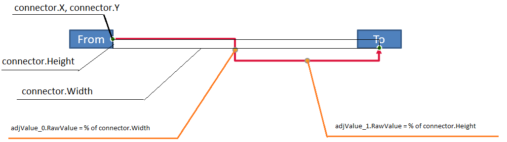
此範例檢查連接線並取得水平與垂直彎曲的調整值:
import com.aspose.slides.*;
import java.awt.Color;

Presentation presentation = new Presentation();
try {
    ISlide slide = presentation.getSlides().get_Item(0);

    IAutoShape sourceShape = slide.getShapes().addAutoShape(ShapeType.Rectangle, 100, 100, 60, 25);
    sourceShape.getTextFrame().setText("From");
    IAutoShape targetShape = slide.getShapes().addAutoShape(ShapeType.Rectangle, 500, 100, 60, 25);
    targetShape.getTextFrame().setText("To");
    IConnector connector = slide.getShapes().addConnector(ShapeType.BentConnector4, 20, 20, 400, 300);

    connector.getLineFormat().setEndArrowheadStyle(LineArrowheadStyle.Triangle);
    connector.getLineFormat().getFillFormat().setFillType(FillType.Solid);
    connector.getLineFormat().getFillFormat().getSolidFillColor().setColor(Color.RED);
    connector.getLineFormat().setWidth(3);
    connector.setStartShapeConnectedTo(sourceShape);
    connector.setStartShapeConnectionSiteIndex(3);
    connector.setEndShapeConnectedTo(targetShape);
    connector.setEndShapeConnectionSiteIndex(2);

    for (int adjustmentIndex = 0; adjustmentIndex < connector.getAdjustments().size(); adjustmentIndex++) {
        IAdjustValue adjustment = connector.getAdjustments().get_Item(adjustmentIndex);
        System.out.println(adjustment.getName() + ": " + adjustment.getType() + ", raw value = " + adjustment.getRawValue());
    }
} finally {
    presentation.dispose();
}
若要同時變更兩個彎曲,先找到每個預期的類型,待全部找到後再修改值:
import com.aspose.slides.*;

Presentation presentation = new Presentation();
try {
    ISlide slide = presentation.getSlides().get_Item(0);

    IAutoShape sourceShape = slide.getShapes().addAutoShape(ShapeType.Rectangle, 100, 100, 60, 25);
    IAutoShape targetShape = slide.getShapes().addAutoShape(ShapeType.Rectangle, 500, 100, 60, 25);
    IConnector connector = slide.getShapes().addConnector(ShapeType.BentConnector4, 20, 20, 400, 300);
    connector.setStartShapeConnectedTo(sourceShape);
    connector.setStartShapeConnectionSiteIndex(3);
    connector.setEndShapeConnectedTo(targetShape);
    connector.setEndShapeConnectionSiteIndex(2);

    IAdjustValue horizontalBend = null;
    IAdjustValue verticalBend = null;
    for (int adjustmentIndex = 0; adjustmentIndex < connector.getAdjustments().size(); adjustmentIndex++) {
        IAdjustValue adjustment = connector.getAdjustments().get_Item(adjustmentIndex);
        if (adjustment.getType() == ShapeAdjustmentType.ConnectorBendPositionX) {
            horizontalBend = adjustment;
        } else if (adjustment.getType() == ShapeAdjustmentType.ConnectorBendPositionY) {
            verticalBend = adjustment;
        }
    }

    if (horizontalBend == null || verticalBend == null) {
        System.out.println("The connector does not expose the expected bend adjustments.");
    } else {
        horizontalBend.setRawValue(horizontalBend.getRawValue() + 20000);
        verticalBend.setRawValue(verticalBend.getRawValue() + 200000);
        presentation.save("connector-adjusted.pptx", SaveFormat.Pptx);
    }
} finally {
    presentation.dispose();
}
結果是水平與垂直段都已移動的連接線:

一旦確定語意類型,即可將其值轉換為連接線框座標。此範例在由兩個彎曲調整控制的垂直段上繪製細長矩形:
import com.aspose.slides.*;

Presentation presentation = new Presentation();
try {
    ISlide slide = presentation.getSlides().get_Item(0);

    IAutoShape sourceShape = slide.getShapes().addAutoShape(ShapeType.Rectangle, 100, 100, 60, 25);
    IAutoShape targetShape = slide.getShapes().addAutoShape(ShapeType.Rectangle, 500, 100, 60, 25);
    IConnector connector = slide.getShapes().addConnector(ShapeType.BentConnector4, 20, 20, 400, 300);
    connector.setStartShapeConnectedTo(sourceShape);
    connector.setStartShapeConnectionSiteIndex(3);
    connector.setEndShapeConnectedTo(targetShape);
    connector.setEndShapeConnectionSiteIndex(2);

    IAdjustValue horizontalBend = null;
    IAdjustValue verticalBend = null;
    for (int adjustmentIndex = 0; adjustmentIndex < connector.getAdjustments().size(); adjustmentIndex++) {
        IAdjustValue adjustment = connector.getAdjustments().get_Item(adjustmentIndex);
        if (adjustment.getType() == ShapeAdjustmentType.ConnectorBendPositionX) {
            horizontalBend = adjustment;
        } else if (adjustment.getType() == ShapeAdjustmentType.ConnectorBendPositionY) {
            verticalBend = adjustment;
        }
    }

    if (horizontalBend == null || verticalBend == null) {
        System.out.println("The connector does not expose the expected bend adjustments.");
    } else {
        float x = connector.getX() + connector.getWidth() * horizontalBend.getRawValue() / 100000f;
        float y = connector.getY();
        float height = connector.getHeight() * verticalBend.getRawValue() / 100000f;
        slide.getShapes().addAutoShape(ShapeType.Rectangle, x, y, 1, height);
        presentation.save("connector-segment-guide.pptx", SaveFormat.Pptx);
    }
} finally {
    presentation.dispose();
}
指南形狀標示計算出的段落:

旋轉或翻轉的連接線
當相同的連接線幾何形狀垂直放置時,其 IShape.getFrame、ShapeFrame.getFlipH 與 ShapeFrame.getFlipV 會影響從框座標到投影片座標的轉換。
此範例建立並調整垂直方向的連接線:
import com.aspose.slides.*;
import java.awt.Color;

Presentation presentation = new Presentation();
try {
    ISlide slide = presentation.getSlides().get_Item(0);

    IAutoShape sourceShape = slide.getShapes().addAutoShape(ShapeType.Rectangle, 100, 100, 60, 25);
    sourceShape.getTextFrame().setText("From");
    IAutoShape targetShape = slide.getShapes().addAutoShape(ShapeType.Rectangle, 100, 400, 60, 25);
    targetShape.getTextFrame().setText("To 1");
    IConnector connector = slide.getShapes().addConnector(ShapeType.BentConnector4, 20, 20, 400, 300);

    connector.getLineFormat().setEndArrowheadStyle(LineArrowheadStyle.Triangle);
    connector.getLineFormat().getFillFormat().setFillType(FillType.Solid);
    connector.getLineFormat().getFillFormat().getSolidFillColor().setColor(new Color(102, 205, 170));
    connector.getLineFormat().setWidth(3);
    connector.setStartShapeConnectedTo(sourceShape);
    connector.setStartShapeConnectionSiteIndex(2);
    connector.setEndShapeConnectedTo(targetShape);
    connector.setEndShapeConnectionSiteIndex(3);

    for (int adjustmentIndex = 0; adjustmentIndex < connector.getAdjustments().size(); adjustmentIndex++) {
        IAdjustValue adjustment = connector.getAdjustments().get_Item(adjustmentIndex);
        if (adjustment.getType() == ShapeAdjustmentType.ConnectorBendPositionX) {
            adjustment.setRawValue(adjustment.getRawValue() + 20000);
        } else if (adjustment.getType() == ShapeAdjustmentType.ConnectorBendPositionY) {
            adjustment.setRawValue(adjustment.getRawValue() + 200000);
        }
    }

    presentation.save("vertical-connector-adjusted.pptx", SaveFormat.Pptx);
} finally {
    presentation.dispose();
}
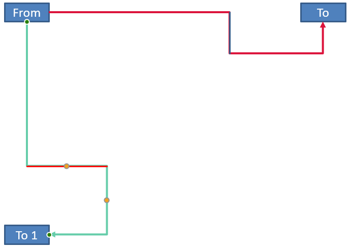
調整後的連接線在形狀之間垂直顯示:
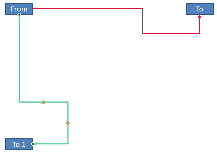
對於任意旋轉角度 alpha,將框座標點 (x, y) 圍繞框中心 (x0, y0) 旋轉:
X = (x - x0) * cos(alpha) - (y - y0) * sin(alpha) + x0
Y = (x - x0) * sin(alpha) + (y - y0) * cos(alpha) + y0
以下程式碼處理本範例使用的 90 度方向,並在相應的連接線段上繪製紅色指南:
import com.aspose.slides.*;
import java.awt.Color;

Presentation presentation = new Presentation();
try {
    ISlide slide = presentation.getSlides().get_Item(0);

    IAutoShape sourceShape = slide.getShapes().addAutoShape(ShapeType.Rectangle, 100, 100, 60, 25);
    IAutoShape targetShape = slide.getShapes().addAutoShape(ShapeType.Rectangle, 100, 400, 60, 25);
    IConnector connector = slide.getShapes().addConnector(ShapeType.BentConnector4, 20, 20, 400, 300);
    connector.setStartShapeConnectedTo(sourceShape);
    connector.setStartShapeConnectionSiteIndex(2);
    connector.setEndShapeConnectedTo(targetShape);
    connector.setEndShapeConnectionSiteIndex(3);

    IAdjustValue horizontalBend = null;
    IAdjustValue verticalBend = null;
    for (int adjustmentIndex = 0; adjustmentIndex < connector.getAdjustments().size(); adjustmentIndex++) {
        IAdjustValue adjustment = connector.getAdjustments().get_Item(adjustmentIndex);
        if (adjustment.getType() == ShapeAdjustmentType.ConnectorBendPositionX) {
            horizontalBend = adjustment;
        } else if (adjustment.getType() == ShapeAdjustmentType.ConnectorBendPositionY) {
            verticalBend = adjustment;
        }
    }

    if (horizontalBend == null || verticalBend == null) {
        System.out.println("The connector does not expose the expected bend adjustments.");
    } else {
        horizontalBend.setRawValue(horizontalBend.getRawValue() + 20000);
        verticalBend.setRawValue(verticalBend.getRawValue() + 200000);

        float x = connector.getX();
        float y = connector.getY();
        if (connector.getFrame().getFlipH() == NullableBool.True) {
            x += connector.getWidth();
        }
        if (connector.getFrame().getFlipV() == NullableBool.True) {
            y += connector.getHeight();
        }

        x += connector.getWidth() * horizontalBend.getRawValue() / 100000f;
        float rotatedX = connector.getFrame().getCenterX() - y + connector.getFrame().getCenterY();
        float rotatedY = x - connector.getFrame().getCenterX() + connector.getFrame().getCenterY();
        float segmentWidth = connector.getHeight() * verticalBend.getRawValue() / 100000f;
        IAutoShape guide = slide.getShapes().addAutoShape(ShapeType.Rectangle, rotatedX, rotatedY, segmentWidth, 1);
        guide.getLineFormat().getFillFormat().setFillType(FillType.Solid);
        guide.getLineFormat().getFillFormat().getSolidFillColor().setColor(Color.RED);

        presentation.save("rotated-connector-segment-guide.pptx", SaveFormat.Pptx);
    }
} finally {
    presentation.dispose();
}
紅色指南在座標轉換後標示出計算出的段落:
这些公式描述了範例中使用的預設,並非通用的連接線模型。於將相同計算套用至不同預設前,請先驗證調整類型、框方向與值範圍。
取得連接線方向角度
直線連接線的方向可由其寬度與高度計算,並考慮水平與垂直翻轉。以下範例回報投影片座標系中,從正水平軸起的順時針角度:
import com.aspose.slides.*;

Presentation presentation = new Presentation();
try {
    ISlide slide = presentation.getSlides().get_Item(0);
    IConnector connector = slide.getShapes().addConnector(ShapeType.StraightConnector1, 100, 100, 200, 100);

    boolean flipH = connector.getFrame().getFlipH() == NullableBool.True;
    boolean flipV = connector.getFrame().getFlipV() == NullableBool.True;
    float deltaX = connector.getWidth() * (flipH ? -1 : 1);
    float deltaY = connector.getHeight() * (flipV ? -1 : 1);
    double angle = Math.atan2(deltaY, deltaX) * 180.0 / Math.PI;

    if (angle < 0) {
        angle += 360;
    }

    System.out.printf("Connector direction: %.2f degrees%n", angle);
} finally {
    presentation.dispose();
}
FAQ
我如何判斷連接線是否能附著於形狀?
檢查形狀的 getConnectionSiteCount 值。正值表示該形狀提供連接點。指派站點索引前,先驗證所選索引是否合法。
我可以僅憑集合索引辨識連接線調整嗎?
索引僅在已知的連接線預設與集合佈局下有意義。變更值前,先檢查 IAdjustValue.getType,若同一語意類型出現多次,請使用 IAdjustValue.getName 取得額外資訊。
當已連接的形狀被刪除會發生什麼?
相應的連接線端會被分離。連接線仍保留在投影片上,可自行刪除、作為自由線定位,或重新附著至其他形狀。
當投影片被複製時,連接線的綁定會被保留嗎?
若連接的形狀與投影片一起被複製,綁定通常會被保留。若僅複製連接線而未複製其目標形狀,則必須再次附著受影響的一端。