
Android でプレゼンテーション シェイプをカスタマイズする
概要
この記事では、編集ポイントとジオメトリパスを使用してシェイプのジオメトリを編集することで、Aspose.Slides のプレゼンテーション シェイプをカスタマイズする方法を説明します。既存のシェイプを変更し、基本的なパス編集操作を実行し、ポイントを追加または削除し、更新されたジオメトリをシェイプに適用するために、GeometryPath と IGeometryPath の使用方法を示します。
また、カスタム シェイプと複合シェイプの作成方法、曲がり角を持つシェイプの構築方法、シェイプ ジオメトリが閉じているかどうかの判定方法、Android のポイント配列を使用したシェイプ要素の検査方法も実演します。
編集ポイントを使用してシェイプを変更する
PowerPoint では、編集ポイント を使用して四角形を変更できます。
- 角を内側または外側に移動する。
- ポイントの曲率を調整する。
- 新しいポイントを追加する。
編集ポイントを使用すると、シェイプの輪郭を変更したり、既存のシェイプを新しいシェイプの基礎として使用したりできます。
シェイプ編集のヒント
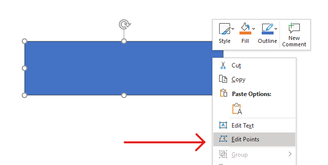
PowerPoint シェイプを編集する際は、次の概念を覚えておいてください。
- シェイプ(またはそのパス)は閉じている場合と開いている場合があります。
- シェイプのパスは、セグメントで接続されたアンカーポイントで構成されます。
- セグメントは直線または曲線のいずれかです。アンカーポイントと制御ハンドルが形状を決定します。
- アンカーポイントはコーナーポイント、直線ポイント、スムーズポイントとして存在します:
- コーナーポイントでは、隣接するセグメントが角度を持って接続できます。
- スムーズポイントでは、2 つの制御ハンドルが一直線上にあり、アンカーポイントから等距離です。
- 直線ポイントでは、2 つの制御ハンドルが一直線上にありますが、アンカーポイントからの距離は異なる場合があります。
- アンカーポイントを移動したりハンドルを調整したりすると、シェイプの輪郭が変わります。
編集ポイントを介して PowerPoint シェイプを編集するには、Aspose.Slides が提供する GeometryPath クラスと IGeometryPath インターフェイスを使用します。
- GeometryPath インスタンスは、IGeometryShape オブジェクトのジオメトリ パスを表します。
- IGeometryShape インスタンスから GeometryPath を取得するには、IGeometryShape.getGeometryPaths メソッドを使用できます。
- シェイプに対して GeometryPath を設定するには、単一パスのシェイプには IGeometryShape.setGeometryPath を、複数パスのシェイプには IGeometryShape.setGeometryPaths を使用します。
- セグメントを追加するには、IGeometryPath 配下のメソッドを使用します。
- IGeometryPath.setStroke と IGeometryPath.setFillMode メソッドを使用して、ジオメトリ パスの外観を設定できます。
- IGeometryPath.getPathData メソッドを使用すると、GeometryShape のジオメトリ パスをパス セグメントの配列として取得できます。
簡単な編集操作
ジオメトリ パスを編集するには、以下のメソッドを使用します。インデックスを受け取るオーバーロードは、パスのセグメント配列内のゼロベース位置にセグメントを挿入します。
| 操作 | メソッド |
|---|---|
| 直線を追加または挿入する。 | GeometryPath.lineTo |
| 2 つの制御点と終点を持つ 3 次ベジエ曲線を追加または挿入する。 | GeometryPath.cubicBezierTo |
| 1 つの制御点と終点を持つ 2 次ベジエ曲線を追加または挿入する。 | GeometryPath.quadraticBezierTo |
| 指定された幅・高さと角度(度)で楕円弧を追加する。 | GeometryPath.arcTo |
| 終点を開始点に接続して現在の図形を閉じる。 | GeometryPath.closeFigure |
| 図形の開始点を設定する。 | GeometryPath.moveTo |
| ゼロベースインデックスのセグメントを削除する。 | GeometryPath.removeAt |
シェイプにカスタムポイントを追加する
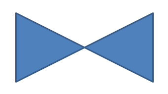
この例は、GeometryPath.lineTo を使用して矩形シェイプに 2 つのポイントを挿入し、IGeometryShape.setGeometryPath で編集されたパスを適用します。座標はシェイプローカルで、2 つの新しいポイントはシェイプの中心にあり、左から 100 ポイント、上から 50 ポイントの位置です。セグメントインデックス 1 と 4 がそれぞれ上辺と下辺に配置され、これらの辺を内側へ引き込んでいます。
import com.aspose.slides.*;

Presentation presentation = new Presentation();
try {
    ISlide slide = presentation.getSlides().get_Item(0);

    IAutoShape shape = slide.getShapes().addAutoShape(ShapeType.Rectangle, 100, 100, 200, 100);

    IGeometryPath geometryPath = shape.getGeometryPaths()[0];
    geometryPath.lineTo(100, 50, 1);
    geometryPath.lineTo(100, 50, 4);

    shape.setGeometryPath(geometryPath);
} finally {
    presentation.dispose();
}
シェイプからポイントを削除する
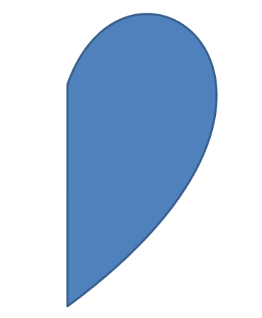
この例は、GeometryPath.removeAt を使用してゼロベースインデックス 2 のセグメントを削除し、ハート形の輪郭を変更します。変更されたパスを IGeometryShape.setGeometryPath で適用すると、シェイプの輪郭が更新されます。
import com.aspose.slides.*;

Presentation presentation = new Presentation();
try {
    ISlide slide = presentation.getSlides().get_Item(0);

    IAutoShape shape = slide.getShapes().addAutoShape(ShapeType.Heart, 100, 100, 300, 300);

    IGeometryPath path = shape.getGeometryPaths()[0];
    path.removeAt(2);

    shape.setGeometryPath(path);
} finally {
    presentation.dispose();
}
カスタム シェイプの作成
この例は、GeometryPath を使用して五角形の星を構築します。外側半径 100 ポイント、内側半径 50 ポイントを交互に設定し、72 度刻みで 5 本の先端を均等に配置します。パスは GeometryPath.closeFigure で閉じられ、IGeometryShape.setGeometryPath を使用して矩形シェイプに適用し、元の輪郭を置き換えます。
import com.aspose.slides.*;
import android.graphics.PointF;
import java.util.ArrayList;
import java.util.List;

List<PointF> points = new ArrayList<>();

float outerRadius = 100f;
float innerRadius = 50f;
int angleStep = 72;

for (int angle = -90; angle < 270; angle += angleStep)
{
    double radians = angle * (Math.PI / 180f);
    double x = outerRadius * Math.cos(radians);
    double y = outerRadius * Math.sin(radians);
    PointF point = new PointF((float)x + outerRadius, (float)y + outerRadius);
    points.add(point);

    radians = Math.PI * (angle + angleStep / 2) / 180.0;
    x = innerRadius * Math.cos(radians);
    y = innerRadius * Math.sin(radians);
    point = new PointF((float)x + outerRadius, (float)y + outerRadius);
    points.add(point);
}

GeometryPath starPath = new GeometryPath();
starPath.moveTo(points.get(0));

for (int i = 1; i < points.size(); i++)
{
    starPath.lineTo(points.get(i));
}

starPath.closeFigure();

Presentation presentation = new Presentation();
try {
    ISlide slide = presentation.getSlides().get_Item(0);

    IAutoShape shape = slide.getShapes().addAutoShape(ShapeType.Rectangle, 100, 100, outerRadius * 2, outerRadius * 2);
    shape.setGeometryPath(starPath);
} finally {
    presentation.dispose();
}

複合カスタム シェイプの作成
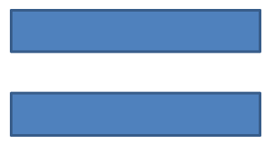
この例は、シェイプの上部 1/3 と下部 1/3 用に 2 つの閉じた GeometryPath オブジェクトを定義します。両方のパスを IGeometryShape.setGeometryPaths で適用すると、中央の 1/3 に隙間のある単一の複合シェイプが作成されます。
import com.aspose.slides.*;

Presentation presentation = new Presentation();
try {
    ISlide slide = presentation.getSlides().get_Item(0);

    IAutoShape shape = slide.getShapes().addAutoShape(ShapeType.Rectangle, 100, 100, 200, 100);

    GeometryPath topPath = new GeometryPath();
    topPath.moveTo(0, 0);
    topPath.lineTo(shape.getWidth(), 0);
    topPath.lineTo(shape.getWidth(), shape.getHeight() / 3);
    topPath.lineTo(0, shape.getHeight() / 3);
    topPath.closeFigure();

    GeometryPath bottomPath = new GeometryPath();
    bottomPath.moveTo(0, shape.getHeight() / 3 * 2);
    bottomPath.lineTo(shape.getWidth(), shape.getHeight() / 3 * 2);
    bottomPath.lineTo(shape.getWidth(), shape.getHeight());
    bottomPath.lineTo(0, shape.getHeight());
    bottomPath.closeFigure();

    shape.setGeometryPaths(new GeometryPath[] { topPath, bottomPath });
} finally {
    presentation.dispose();
}
曲がり角付きカスタム シェイプの作成
この例は、直線セグメントと GeometryPath.arcTo を組み合わせて、内側に曲がった角を持つシェイプを作成します。各角のサイズはアークの幅と高さをポイントで設定し、-90 度のスイープで反時計回りの 1/4 楕円を描きます。完成したパスは IGeometryShape.setGeometryPath で適用され、プレゼンテーションは PPTX 形式で保存されます。
import com.aspose.slides.*;
import android.graphics.PointF;

float shapeX = 20f;
float shapeY = 20f;
float shapeWidth = 300f;
float shapeHeight = 200f;

float leftTopSize = 50f;
float rightTopSize = 20f;
float rightBottomSize = 40f;
float leftBottomSize = 10f;

Presentation presentation = new Presentation();
try {
    ISlide slide = presentation.getSlides().get_Item(0);

    IAutoShape shape = slide.getShapes().addAutoShape(ShapeType.Custom, shapeX, shapeY, shapeWidth, shapeHeight);

    PointF topLeft = new PointF(leftTopSize, 0);
    PointF topRight = new PointF(shapeWidth - rightTopSize, 0);
    PointF rightBottom = new PointF(shapeWidth, shapeHeight - rightBottomSize);
    PointF bottomLeft = new PointF(leftBottomSize, shapeHeight);
    PointF leftTop = new PointF(0, leftTopSize);

    GeometryPath geometryPath = new GeometryPath();
    geometryPath.moveTo(topLeft);
    geometryPath.lineTo(topRight);
    geometryPath.arcTo(rightTopSize, rightTopSize, 180, -90);
    geometryPath.lineTo(rightBottom);
    geometryPath.arcTo(rightBottomSize, rightBottomSize, -90, -90);
    geometryPath.lineTo(bottomLeft);
    geometryPath.arcTo(leftBottomSize, leftBottomSize, 0, -90);
    geometryPath.lineTo(leftTop);
    geometryPath.arcTo(leftTopSize, leftTopSize, 90, -90);
    geometryPath.closeFigure();

    shape.setGeometryPath(geometryPath);

    presentation.save("output.pptx", SaveFormat.Pptx);
} finally {
    presentation.dispose();
}
シェイプ ジオメトリが閉じているかどうかの判定
以下のヘルパーは、すべての非空ジオメトリ パスが閉じるセグメントで終わっているかどうかをチェックします。[IGeometryPath.getPathData](https://reference.aspose.com/slides/androidjava/com.aspose.slides/igeometrypath/#getPathData--) を読み取り、最終セグメントの [IPathSegment.getPathCommand](https://reference.aspose.com/slides/androidjava/com.aspose.slides/ipathsegment/#getPathCommand--) が [PathCommandType.Close](https://reference.aspose.com/slides/androidjava/com.aspose.slides/pathcommandtype/) と一致するか比較します。非空パスが存在しない場合は false を返します。このチェックは各パスの最終コマンドだけを対象とし、パス内のすべてのサブフィギュアは検査しません。例では矩形に対して true が出力されます。
import com.aspose.slides.*;

class GeometryInspector {
    boolean isGeometryClosed(IGeometryShape geometryShape) {
        boolean hasNonemptyPath = false;

        for (IGeometryPath geometryPath : geometryShape.getGeometryPaths()) {
            IPathSegment[] segments = geometryPath.getPathData();
            if (segments.length == 0) {
                continue;
            }

            hasNonemptyPath = true;
            IPathSegment lastSegment = segments[segments.length - 1];
            if (lastSegment.getPathCommand() != PathCommandType.Close) {
                return false;
            }
        }

        return hasNonemptyPath;
    }
}

Presentation presentation = new Presentation();
try {
    ISlide slide = presentation.getSlides().get_Item(0);

    IAutoShape shape = slide.getShapes().addAutoShape(ShapeType.Rectangle, 100, 100, 200, 100);

    GeometryInspector inspector = new GeometryInspector();
    boolean closed = inspector.isGeometryClosed(shape);
    System.out.println(closed);
} finally {
    presentation.dispose();
}
シェイプ要素の抽出と検査
IGeometryShape.createShapeElements を使用して、パスポイントとポイントタイプを含む要素として既存シェイプを検査できます。返された各 IShapeElement を ShapeElement にキャストし、[getPathPoints](https://reference.aspose.com/slides/androidjava/com.aspose.slides/shapeelement/#getPathPoints--) と [getPathTypes](https://reference.aspose.com/slides/androidjava/com.aspose.slides/shapeelement/#getPathTypes--) メソッドでポイント配列とタイプ配列を取得します。この表現は輪郭解析やカスタム描画ツールへのジオメトリ受け渡しに便利です。
例では input.pptx を開き、最初のスライド上の最初のジオメトリ シェイプを直接取得し、そのパス セグメントを出力します。直線と曲線の両方を含むシェイプが含まれるプレゼンテーションを使用すると、両方の出力が確認できます。グループ内部は検索されません。
import com.aspose.slides.*;
import android.graphics.PointF;

Presentation presentation = new Presentation("input.pptx");
try {
    ISlide slide = presentation.getSlides().get_Item(0);

    IGeometryShape shape = null;
    for (IShape candidate : slide.getShapes()) {
        if (candidate instanceof IGeometryShape) {
            shape = (IGeometryShape) candidate;
            break;
        }
    }

    if (shape == null) {
        System.out.println("No geometry shape found on the first slide.");
    } else {
        for (IShapeElement element : shape.createShapeElements()) {
            ShapeElement shapeElement = (ShapeElement) element;
            PointF[] points = shapeElement.getPathPoints();
            byte[] types = shapeElement.getPathTypes();
            System.out.println("Shape element:");

            for (int i = 0; i < points.length; i++) {
                int pointType = types[i] & 0x07; // フラグを除いたセグメントタイプを保持します。
                switch (pointType) {
                    case 0:
                        System.out.println("Start figure at " + points[i]);
                        break;
                    case 1:
                        System.out.println("Line to " + points[i]);
                        break;
                    case 3:
                        System.out.println("Cubic Bezier: controls " + points[i] + ", " + points[i + 1] + "; end " + points[i + 2]);
                        i += 2; // 制御点2つと終点を消費します。
                        break;
                }

                if ((types[i] & 0x80) != 0) {
                    System.out.println("Close subpath back to its starting point.");
                }
            }
        }
    }
} finally {
    presentation.dispose();
}
配列はインデックスで対応します: points[i] は点、types[i] はその役割を表します。タイプ 0 は図形の開始、タイプ 1 は前の点から現在の点への直線を示します。3 次ベジエ セグメントは前の終点から開始し、タイプ 3 のエントリが 3 つ続きます: 2 つの制御点と新しい終点です。ループはこれら 3 エントリをまとめて消費し、終点が閉じているかどうかを確認します。
ポイントタイプにはフラグも含まれます。0x07 でセグメント種別を判別し、0x80 を別途テストして閉じたサブパスを検出します。例として 129 (0x81) はサブパスを閉じる直線終点、131 (0x83) はサブパスを閉じるベジエ終点を意味します。Java はこれらを符号付きバイトで保持するため、マスク処理でビット値を保持します。1 や 3 だけと比較するとこれらのケースを見落とします。ダッシュ (0x10) やマーカー (0x20) などの他フラグは基礎セグメント種別を変えません。
座標と変換 ポイントはポイント単位 (1/72 インチ) で測定され、X は右方向、Y は下方向に増加します。グループ化されていないシェイプの場合、抽出された座標は既に [getX](https://reference.aspose.com/slides/androidjava/com.aspose.slides/shape/#getX--) と [getY](https://reference.aspose.com/slides/androidjava/com.aspose.slides/shape/#getY--) が返す位置を含み、現在の幅と高さを反映しています。例として、未回転の矩形が (100, 200) に左上があり、サイズが 120 × 80 の場合、輪郭の境界は (100, 200)–(220, 280) です。シェイプの位置を再度加算しないでください。未回転フレームに対して相対座標を得るには X と Y を引き算します。
抽出されたポイントは [getRotation](https://reference.aspose.com/slides/androidjava/com.aspose.slides/shape/#getRotation--) による回転や水平・垂直フリップは適用されません。表示された輪郭を再現するには、シェイプの中心を基点にこれらの変換を適用してください。グループ化されたシェイプの場合は、グループ座標マッピングと変換も考慮し、抽出ポイントが最終スライド座標であると仮定したり、すでに子フレームに反映されている平行移動やスケールを二重に適用したりしないでください。
検査と編集の違い 抽出された配列は輪郭を記述しますが、配列を変更しても元のシェイプは更新されません。ポイント/タイプ配列が必要な解析や描画コードにはこの方法を選択してください。シェイプのローカル座標系でジオメトリ コマンドが必要、またはジオメトリを編集したい場合は [getGeometryPaths](https://reference.aspose.com/slides/androidjava/com.aspose.slides/igeometryshape/#getGeometryPaths--) を使用し、編集後は [setGeometryPath](https://reference.aspose.com/slides/androidjava/com.aspose.slides/igeometryshape/#setGeometryPath-com.aspose.slides.IGeometryPath-) または [setGeometryPaths](https://reference.aspose.com/slides/androidjava/com.aspose.slides/igeometryshape/#setGeometryPaths-com.aspose.slides.IGeometryPath---) で適用してください。
よくある質問
ジオメトリを置き換えた後、塗りつぶしと輪郭はどうなりますか?
スタイルはシェイプに残り、輪郭だけが変更されます。塗りつぶしと輪郭は新しいジオメトリに自動的に適用されます。
ジオメトリと一緒にカスタム シェイプを正しく回転させるにはどうすればよいですか?
シェイプの [setRotation](https://reference.aspose.com/slides/androidjava/com.aspose.slides/shape/#setRotation-float-) メソッドを使用してください。ジオメトリはシェイプの座標系にバインドされているため、シェイプと共に回転します。
カスタム シェイプを画像に変換して「ロック」できますか?
はい。対象の slide 領域または shape 自体をラスター形式でエクスポートすれば、複雑なジオメトリの後続作業が簡素化されます。