
在 Android 上自定义演示文稿形状
概述
本文介绍了如何通过编辑点和几何路径来编辑形状几何,从而在 Aspose.Slides 中自定义演示文稿形状。它展示了如何使用GeometryPath和IGeometryPath修改现有形状、执行基本的路径编辑操作、添加或删除点,并将更新后的几何应用回形状。
它还演示了如何创建自定义和复合形状、构建带有圆角的形状、判断形状几何是否闭合,以及使用 Android 点数组检查形状元素。
使用编辑点更改形状
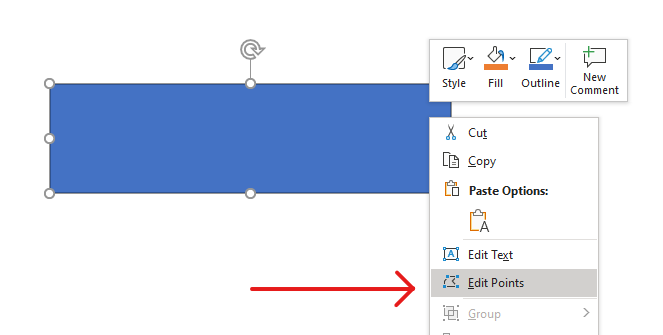
在 PowerPoint 中,您可以使用编辑点来修改正方形:
- 将角向内或向外移动。
- 调整点处的曲率。
- 添加新点。
编辑点可让您修改形状的轮廓,或以现有形状为基础创建新形状。
形状编辑技巧
编辑 PowerPoint 形状时,请记住以下概念:
- 形状(或其路径)可以是闭合的,也可以是开放的。
- 形状的路径由通过线段连接的锚点组成。
- 线段可以是直线或曲线。锚点和控制柄决定其形状。
- 锚点有角点、直点和光滑点三种形式:
- 在角点,相邻线段可以形成一个角度。
- 在光滑点,两个控制柄共线且距离锚点相等。
- 在直点,两个控制柄仍共线,但距离锚点可以不同。
- 移动锚点或调整其控制柄会改变形状的轮廓。
要通过编辑点编辑 PowerPoint 形状,Aspose.Slides 提供了GeometryPath类和IGeometryPath接口。
- 一个GeometryPath实例表示IGeometryShape对象的几何路径。
- 要从IGeometryShape实例获取GeometryPath,可以使用IGeometryShape.getGeometryPaths方法。
- 要为形状设置GeometryPath,可以使用以下方法:对于单一路径的形状使用IGeometryShape.setGeometryPath,对于多路径的形状使用IGeometryShape.setGeometryPaths。
- 要添加线段,可以使用IGeometryPath下的方法。
- 使用IGeometryPath.setStroke和IGeometryPath.setFillMode方法,可以设置几何路径的外观。
- 使用IGeometryPath.getPathData方法,可以将GeometryShape的几何路径检索为路径段数组。
简易编辑操作
使用以下方法编辑几何路径。接受索引的重载将在路径的线段数组中的该零基位置插入线段。
| 操作 | 方法 |
|---|---|
| 追加或插入直线。 | GeometryPath.lineTo |
| 追加或插入具有两个控制点和终点的三次贝塞尔曲线。 | GeometryPath.cubicBezierTo |
| 追加或插入具有一个控制点和终点的二次贝塞尔曲线。 | GeometryPath.quadraticBezierTo |
| 追加具有指定尺寸和角度(度)的椭圆弧。 | GeometryPath.arcTo |
| 通过将终点连接到起点来闭合当前图形。 | GeometryPath.closeFigure |
| 设置图形的起始点。 | GeometryPath.moveTo |
| 删除指定的(零基)索引处的线段。 | GeometryPath.removeAt |
向形状添加自定义点
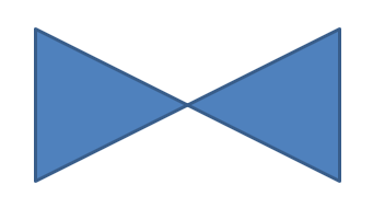
此示例使用GeometryPath.lineTo在矩形形状中插入两个点,并使用IGeometryShape.setGeometryPath应用编辑后的路径。坐标相对于形状本身:两个新点位于形状中心,离左边 100 点,离顶部 50 点。线段索引 1 和 4 将它们放置在顶部和底部边缘,从而将这些边缘向内拉。
import com.aspose.slides.*;

Presentation presentation = new Presentation();
try {
    ISlide slide = presentation.getSlides().get_Item(0);

    IAutoShape shape = slide.getShapes().addAutoShape(ShapeType.Rectangle, 100, 100, 200, 100);

    IGeometryPath geometryPath = shape.getGeometryPaths()[0];
    geometryPath.lineTo(100, 50, 1);
    geometryPath.lineTo(100, 50, 4);

    shape.setGeometryPath(geometryPath);
} finally {
    presentation.dispose();
}
从形状删除点
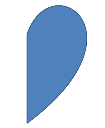
此示例通过使用GeometryPath.removeAt删除零基索引 2 处的线段来更改心形轮廓。使用IGeometryShape.setGeometryPath应用修改后的路径,可更新形状的轮廓。
import com.aspose.slides.*;

Presentation presentation = new Presentation();
try {
    ISlide slide = presentation.getSlides().get_Item(0);

    IAutoShape shape = slide.getShapes().addAutoShape(ShapeType.Heart, 100, 100, 300, 300);

    IGeometryPath path = shape.getGeometryPaths()[0];
    path.removeAt(2);

    shape.setGeometryPath(path);
} finally {
    presentation.dispose();
}
创建自定义形状
此示例使用GeometryPath构建一个五角星。交替的外半径和内半径分别为 100 点和 50 点定义了尖角和凹进;72 度的步进将五个尖角均匀间隔。路径通过GeometryPath.closeFigure闭合,并使用IGeometryShape.setGeometryPath应用到矩形形状,替换其轮廓。
import com.aspose.slides.*;
import android.graphics.PointF;
import java.util.ArrayList;
import java.util.List;

List<PointF> points = new ArrayList<>();

float outerRadius = 100f;
float innerRadius = 50f;
int angleStep = 72;

for (int angle = -90; angle < 270; angle += angleStep)
{
    double radians = angle * (Math.PI / 180f);
    double x = outerRadius * Math.cos(radians);
    double y = outerRadius * Math.sin(radians);
    PointF point = new PointF((float)x + outerRadius, (float)y + outerRadius);
    points.add(point);

    radians = Math.PI * (angle + angleStep / 2) / 180.0;
    x = innerRadius * Math.cos(radians);
    y = innerRadius * Math.sin(radians);
    point = new PointF((float)x + outerRadius, (float)y + outerRadius);
    points.add(point);
}

GeometryPath starPath = new GeometryPath();
starPath.moveTo(points.get(0));

for (int i = 1; i < points.size(); i++)
{
    starPath.lineTo(points.get(i));
}

starPath.closeFigure();

Presentation presentation = new Presentation();
try {
    ISlide slide = presentation.getSlides().get_Item(0);

    IAutoShape shape = slide.getShapes().addAutoShape(ShapeType.Rectangle, 100, 100, outerRadius * 2, outerRadius * 2);
    shape.setGeometryPath(starPath);
} finally {
    presentation.dispose();
}

创建复合自定义形状
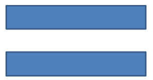
此示例为形状的上三分之一和下三分之一定义了两个闭合的GeometryPath对象。使用IGeometryShape.setGeometryPaths同时应用两条路径,可创建一个在中间三分之一位置留有间隙的单一复合形状。
import com.aspose.slides.*;

Presentation presentation = new Presentation();
try {
    ISlide slide = presentation.getSlides().get_Item(0);

    IAutoShape shape = slide.getShapes().addAutoShape(ShapeType.Rectangle, 100, 100, 200, 100);

    GeometryPath topPath = new GeometryPath();
    topPath.moveTo(0, 0);
    topPath.lineTo(shape.getWidth(), 0);
    topPath.lineTo(shape.getWidth(), shape.getHeight() / 3);
    topPath.lineTo(0, shape.getHeight() / 3);
    topPath.closeFigure();

    GeometryPath bottomPath = new GeometryPath();
    bottomPath.moveTo(0, shape.getHeight() / 3 * 2);
    bottomPath.lineTo(shape.getWidth(), shape.getHeight() / 3 * 2);
    bottomPath.lineTo(shape.getWidth(), shape.getHeight());
    bottomPath.lineTo(0, shape.getHeight());
    bottomPath.closeFigure();

    shape.setGeometryPaths(new GeometryPath[] { topPath, bottomPath });
} finally {
    presentation.dispose();
}
创建带圆角的自定义形状
此示例将直线段与GeometryPath.arcTo相结合,创建一个内凹圆角的形状。每个角的大小以点为单位设置弧的宽度和高度,-90 度的弧度绘制逆时针四分之一椭圆。完成的路径使用IGeometryShape.setGeometryPath应用,并将演示文稿另存为 PPTX 格式。
import com.aspose.slides.*;
import android.graphics.PointF;

float shapeX = 20f;
float shapeY = 20f;
float shapeWidth = 300f;
float shapeHeight = 200f;

float leftTopSize = 50f;
float rightTopSize = 20f;
float rightBottomSize = 40f;
float leftBottomSize = 10f;

Presentation presentation = new Presentation();
try {
    ISlide slide = presentation.getSlides().get_Item(0);

    IAutoShape shape = slide.getShapes().addAutoShape(ShapeType.Custom, shapeX, shapeY, shapeWidth, shapeHeight);

    PointF topLeft = new PointF(leftTopSize, 0);
    PointF topRight = new PointF(shapeWidth - rightTopSize, 0);
    PointF rightBottom = new PointF(shapeWidth, shapeHeight - rightBottomSize);
    PointF bottomLeft = new PointF(leftBottomSize, shapeHeight);
    PointF leftTop = new PointF(0, leftTopSize);

    GeometryPath geometryPath = new GeometryPath();
    geometryPath.moveTo(topLeft);
    geometryPath.lineTo(topRight);
    geometryPath.arcTo(rightTopSize, rightTopSize, 180, -90);
    geometryPath.lineTo(rightBottom);
    geometryPath.arcTo(rightBottomSize, rightBottomSize, -90, -90);
    geometryPath.lineTo(bottomLeft);
    geometryPath.arcTo(leftBottomSize, leftBottomSize, 0, -90);
    geometryPath.lineTo(leftTop);
    geometryPath.arcTo(leftTopSize, leftTopSize, 90, -90);
    geometryPath.closeFigure();

    shape.setGeometryPath(geometryPath);

    presentation.save("output.pptx", SaveFormat.Pptx);
} finally {
    presentation.dispose();
}
确定形状几何是否闭合
以下辅助方法检查每个非空几何路径是否以闭合线段结束。它读取IGeometryPath.getPathData并将最终线段的IPathSegment.getPathCommand与PathCommandType.Close进行比较。当不存在非空路径时返回 false。此检查每条路径的最终命令;它不会检查路径内部的每个子图形。示例对矩形打印 true。
import com.aspose.slides.*;

class GeometryInspector {
    boolean isGeometryClosed(IGeometryShape geometryShape) {
        boolean hasNonemptyPath = false;

        for (IGeometryPath geometryPath : geometryShape.getGeometryPaths()) {
            IPathSegment[] segments = geometryPath.getPathData();
            if (segments.length == 0) {
                continue;
            }

            hasNonemptyPath = true;
            IPathSegment lastSegment = segments[segments.length - 1];
            if (lastSegment.getPathCommand() != PathCommandType.Close) {
                return false;
            }
        }

        return hasNonemptyPath;
    }
}

Presentation presentation = new Presentation();
try {
    ISlide slide = presentation.getSlides().get_Item(0);

    IAutoShape shape = slide.getShapes().addAutoShape(ShapeType.Rectangle, 100, 100, 200, 100);

    GeometryInspector inspector = new GeometryInspector();
    boolean closed = inspector.isGeometryClosed(shape);
    System.out.println(closed);
} finally {
    presentation.dispose();
}
提取并检查形状元素
使用IGeometryShape.createShapeElements可将现有形状检查为包含路径点和点类型的元素。将每个返回的IShapeElement强制转换为ShapeElement ,通过getPathPoints和getPathTypes方法获取点数组和类型数组。这种表示方式对轮廓分析或将几何传递给自定义绘图工具非常有用。
示例打开 input.pptx,直接在第一张幻灯片上找到第一个几何形状,并打印其路径线段。使用包含直线段和曲线段的形状进行演示,可看到两种输出。它不会在组内部搜索。
import com.aspose.slides.*;
import android.graphics.PointF;

Presentation presentation = new Presentation("input.pptx");
try {
    ISlide slide = presentation.getSlides().get_Item(0);

    IGeometryShape shape = null;
    for (IShape candidate : slide.getShapes()) {
        if (candidate instanceof IGeometryShape) {
            shape = (IGeometryShape) candidate;
            break;
        }
    }

    if (shape == null) {
        System.out.println("No geometry shape found on the first slide.");
    } else {
        for (IShapeElement element : shape.createShapeElements()) {
            ShapeElement shapeElement = (ShapeElement) element;
            PointF[] points = shapeElement.getPathPoints();
            byte[] types = shapeElement.getPathTypes();
            System.out.println("Shape element:");

            for (int i = 0; i < points.length; i++) {
                int pointType = types[i] & 0x07; // 保留线段类型,排除标志。
                switch (pointType) {
                    case 0:
                        System.out.println("Start figure at " + points[i]);
                        break;
                    case 1:
                        System.out.println("Line to " + points[i]);
                        break;
                    case 3:
                        System.out.println("Cubic Bezier: controls " + points[i] + ", " + points[i + 1] + "; end " + points[i + 2]);
                        i += 2; // Consume both control points and the endpoint.
                        break;
                }

                if ((types[i] & 0x80) != 0) {
                    System.out.println("Close subpath back to its starting point.");
                }
            }
        }
    }
} finally {
    presentation.dispose();
}
数组按索引对应:points[i] 是一个点,types[i] 描述其角色。类型 0 开始一个图形,类型 1 绘制从前一点到当前点的直线。三次贝塞尔线段从前一个终点开始,使用连续的三个类型为 3 的条目:两个控制点后跟新的终点。循环一次性消费这三个条目,并检查终点是否闭合。
点类型还包含标志。使用 0x07 掩码可识别线段类型,使用 0x80 单独检测闭合子路径。例如,129(0x81)表示闭合子路径的直线端点,131(0x83)表示闭合的贝塞尔端点。Java 将这些标志存储在有符号字节中;掩码操作可保留预期的位值。仅与 1 或 3 比较原始值会遗漏这些情况。其他标志,如虚线 (0x10) 和标记 (0x20),不会改变基本的线段类型。
坐标和变换。 点以点为单位(1/72 英寸),X 向右增大,Y 向下增大。对于未分组的形状,提取的坐标已包含由getX和getY返回的位置,并反映其当前宽度和高度。例如,位于 (100, 200)、大小为 120 × 80 的未旋转矩形,其轮廓边界为 (100, 200)–(220, 280)。不要再次添加形状的位置。减去其 X 和 Y 可获得相对于其未旋转框架的坐标。
提取的点不应用形状的旋转(由getRotation 返回)或水平、垂直翻转。要重现显示的轮廓,需要围绕形状中心应用这些变换。对于分组形状,还需考虑组坐标映射和变换;不要假设提取的点就是最终渲染的幻灯片坐标,亦不要在已在子框架中反映的情况下再次进行平移或缩放。
检查 vs 编辑。 提取的数组描述轮廓;修改它们不会更新原始形状。当您的分析或绘图代码需要点/类型数组时,请选择此方法。需要在形状的本地坐标系中获取几何命令或编辑几何时,请使用getGeometryPaths。通过setGeometryPath或setGeometryPaths应用编辑后的路径。
常见问题
替换几何后,填充和轮廓会怎样?
样式仍然保留在形状上;仅轮廓发生变化。填充和轮廓会自动应用到新的几何上。
如何正确地连同几何一起旋转自定义形状?
使用形状的setRotation方法;几何会随形状一起旋转,因为它绑定在形状自己的坐标系上。
我能将自定义形状转换为图像以“锁定”结果吗?