
C++에서 프레젠테이션 모양 사용자 지정
개요
이 문서에서는 편집 포인트와 기하 경로를 사용하여 모양 기하학을 편집함으로써 Aspose.Slides에서 프레젠테이션 모양을 사용자 지정하는 방법을 설명합니다. GeometryPath 및 IGeometryPath를 사용하여 기존 모양을 수정하고, 기본 경로 편집 작업을 수행하며, 포인트를 추가하거나 제거하고, 업데이트된 기하학을 모양에 적용하는 방법을 보여줍니다.
편집 포인트를 사용하여 모양 변경
정사각형을 예로 들어보겠습니다. PowerPoint에서 편집 포인트를 사용하면
- 정사각형 모서리를 안쪽 또는 바깥쪽으로 이동
- 모서리 또는 포인트의 곡률 지정
- 정사각형에 새로운 포인트 추가
- 정사각형의 포인트를 조작 등
과 같이 할 수 있습니다.
본질적으로 이러한 작업은 모든 모양에 적용할 수 있습니다. 편집 포인트를 사용하면 기존 모양을 변경하거나 기존 모양을 기반으로 새로운 모양을 만들 수 있습니다.
모양 편집 팁
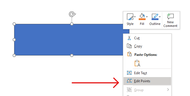
PowerPoint 모양을 편집 포인트를 통해 편집하기 시작하기 전에, 다음과 같은 모양 관련 사항을 고려하십시오:
- 모양(또는 그 경로)은 닫힌 형태이거나 열린 형태일 수 있습니다.
- 닫힌 모양은 시작점이나 끝점이 없습니다. 열린 모양은 시작점과 끝점을 가집니다.
- 모든 모양은 최소 2개의 앵커 포인트가 선으로 연결되어 구성됩니다.
- 선은 직선이거나 곡선일 수 있습니다. 앵커 포인트가 선의 형태를 결정합니다.
- 앵커 포인트는 코너 포인트, 직선 포인트 또는 스무스 포인트로 존재합니다:
- 코너 포인트는 두 개의 직선이 각을 이루며 만나는 지점입니다.
- 스무스 포인트는 두 개의 핸들이 직선 상에 존재하고 선의 구간이 부드러운 곡선으로 연결되는 지점입니다. 이 경우 모든 핸들은 앵커 포인트와 동일한 거리를 두고 떨어져 있습니다.
- 직선 포인트는 두 개의 핸들이 직선 상에 존재하고 그 선의 구간이 부드러운 곡선으로 연결되는 지점입니다. 이 경우 핸들은 앵커 포인트와 동일한 거리를 유지할 필요가 없습니다.
- 앵커 포인트를 이동하거나 편집(선의 각도를 변경)하면 모양의 외형을 바꿀 수 있습니다.
편집 포인트를 통해 PowerPoint 모양을 편집하려면, Aspose.Slides에서 GeometryPath 클래스와 IGeometryPath 인터페이스를 제공합니다.
- GeometryPath 인스턴스는 IGeometryShape 객체의 기하 경로를 나타냅니다.
IGeometryShape인스턴스에서GeometryPath를 가져오려면, IGeometryShape::GetGeometryPaths 메서드를 사용할 수 있습니다.- 모양에
GeometryPath를 설정하려면, 다음 메서드를 사용할 수 있습니다: 솔리드 모양의 경우 IGeometryShape::SetGeometryPath(), 복합 모양의 경우 IGeometryShape::SetGeometryPaths(). - 세그먼트를 추가하려면, IGeometryPath 아래의 메서드를 사용할 수 있습니다.
- IGeometryPath::set_Stroke() 및 IGeometryPath::set_FillMode() 메서드를 사용하여 기하 경로의 외관을 설정할 수 있습니다.
- IGeometryPath::get_PathData() 메서드를 사용하여
GeometryShape의 기하 경로를 경로 세그먼트 배열로 가져올 수 있습니다. - 추가적인 모양 기하학 사용자 지정 옵션에 접근하려면, GeometryPath를 GraphicsPath로 변환할 수 있습니다.
- GeometryPathToGraphicsPath 및 GraphicsPathToGeometryPath 메서드(ShapeUtil 클래스에서)를 사용하여 GeometryPath를 GraphicsPath와 상호 변환할 수 있습니다.
간단한 편집 작업
다음 C++ 코드는 다음과 같이 수행하는 방법을 보여 줍니다.
라인 추가 경로 끝에
void LineTo(PointF point);
void LineTo(float x, float y);
라인 추가 지정된 위치에 경로에:
void LineTo(PointF point, uint32_t index);
void LineTo(float x, float y, uint32_t index);
큐빅 베지에 곡선 추가 경로 끝에:
void CubicBezierTo(PointF point1, PointF point2, PointF point3);
void CubicBezierTo(float x1, float y1, float x2, float y2, float x3, float y3);
큐빅 베지에 곡선 추가 지정된 위치에 경로에:
void CubicBezierTo(PointF point1, PointF point2, PointF point3, uint32_t index);
void CubicBezierTo(float x1, float y1, float x2, float y2, float x3, float y3, uint32_t index);
2차 베지에 곡선 추가 경로 끝에:
void QuadraticBezierTo(PointF point1, PointF point2);
void QuadraticBezierTo(float x1, float y1, float x2, float y2);
2차 베지에 곡선 추가 지정된 위치에 경로에:
void QuadraticBezierTo(PointF point1, PointF point2, uint32_t index);
void QuadraticBezierTo(float x1, float y1, float x2, float y2, uint32_t index);
주어진 호 추가 경로에:
void ArcTo(float width, float heigth, float startAngle, float sweepAngle);
현재 도형 닫기 경로의:
void CloseFigure();
다음 포인트 위치 설정:
void MoveTo(PointF point);
void MoveTo(float x, float y);
경로 세그먼트 제거 지정 인덱스에서:
void RemoveAt(int32_t index);
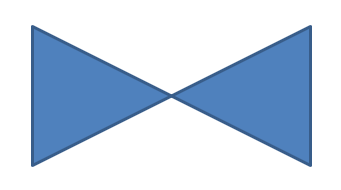
모양에 사용자 지정 포인트 추가
- GeometryShape 클래스의 인스턴스를 생성하고 ShapeType.Rectangle 유형을 설정합니다.
- 모양에서 GeometryPath 클래스의 인스턴스를 가져옵니다.
- 경로의 상단 두 포인트 사이에 새로운 포인트를 추가합니다.
- 경로의 하단 두 포인트 사이에 새로운 포인트를 추가합니다.
- 경로를 모양에 적용합니다.
다음 C++ 코드는 모양에 사용자 지정 포인트를 추가하는 방법을 보여 줍니다:
SharedPtr<Presentation> pres = System::MakeObject<Presentation>();

SharedPtr<IShapeCollection> shapes = pres->get_Slides()->idx_get(0)->get_Shapes();
SharedPtr<GeometryShape> shape = System::ExplicitCast<GeometryShape>(shapes->AddAutoShape(ShapeType::Rectangle, 100.0f, 100.0f, 200.0f, 100.0f));

SharedPtr<IGeometryPath> geometryPath = shape->GetGeometryPaths()->idx_get(0);

geometryPath->LineTo(100.0f, 50.0f, 1);
geometryPath->LineTo(100.0f, 50.0f, 4);
shape->SetGeometryPath(geometryPath);
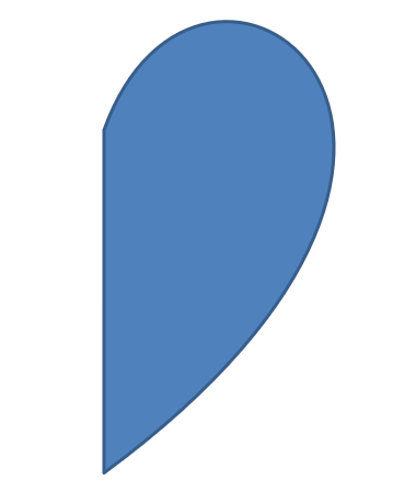
모양에서 포인트 제거
- GeometryShape 클래스의 인스턴스를 생성하고 ShapeType.Heart 유형을 설정합니다.
- 모양에서 GeometryPath 클래스의 인스턴스를 가져옵니다.
- 경로의 세그먼트를 제거합니다.
- 경로를 모양에 적용합니다.
다음 C++ 코드는 모양에서 포인트를 제거하는 방법을 보여 줍니다:
SharedPtr<Presentation> pres = System::MakeObject<Presentation>();

SharedPtr<IShapeCollection> shapes = pres->get_Slides()->idx_get(0)->get_Shapes();
SharedPtr<GeometryShape> shape = System::ExplicitCast<GeometryShape>(shapes->AddAutoShape(ShapeType::Heart, 100.0f, 100.0f, 300.0f, 300.0f));

SharedPtr<IGeometryPath> path = shape->GetGeometryPaths()->idx_get(0);
path->RemoveAt(2);
shape->SetGeometryPath(path);
사용자 지정 모양 만들기
- 모양에 대한 포인트를 계산합니다.
- GeometryPath 클래스의 인스턴스를 생성합니다.
- 포인트로 경로를 채웁니다.
- GeometryShape 클래스의 인스턴스를 생성합니다.
- 경로를 모양에 적용합니다.
다음 C++ 코드는 사용자 지정 모양을 만드는 방법을 보여 줍니다:
SharedPtr<List<PointF>> points = System::MakeObject<List<PointF>>();

float R = 100.0f, r = 50.0f;
int32_t step = 72;

for (int32_t angle = -90; angle < 270; angle += step)
{
    double radians = angle * (Math::PI / 180.f);
    double x = outerRadius * Math::Cos(radians);
    double y = outerRadius * Math::Sin(radians);
    points->Add(PointF((float)x + outerRadius, (float)y + outerRadius));

    radians = Math::PI * (angle + step / 2) / 180.0;
    x = innerRadiusr * Math::Cos(radians);
    y = innerRadiusr * Math::Sin(radians);
    points->Add(PointF((float)x + outerRadius, (float)y + outerRadius));
}

SharedPtr<GeometryPath> starPath = System::MakeObject<GeometryPath>();
starPath->MoveTo(points->idx_get(0));

for (int32_t i = 1; i < points->get_Count(); i++)
{
    starPath->LineTo(points->idx_get(i));
}

starPath->CloseFigure();

SharedPtr<Presentation> pres = System::MakeObject<Presentation>();

SharedPtr<IShapeCollection> shapes = pres->get_Slides()->idx_get(0)->get_Shapes();
SharedPtr<GeometryShape> shape = System::ExplicitCast<GeometryShape>(shapes->AddAutoShape(ShapeType::Rectangle, 100.0f, 100.0f, R * 2, R * 2));

shape->SetGeometryPath(starPath);

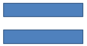
복합 사용자 지정 모양 만들기
- GeometryShape 클래스의 인스턴스를 생성합니다.
- GeometryPath 클래스의 첫 번째 인스턴스를 생성합니다.
- GeometryPath 클래스의 두 번째 인스턴스를 생성합니다.
- 경로들을 모양에 적용합니다.
다음 C++ 코드는 복합 사용자 지정 모양을 만드는 방법을 보여 줍니다:
SharedPtr<Presentation> pres = System::MakeObject<Presentation>();

SharedPtr<IShapeCollection> shapes = pres->get_Slides()->idx_get(0)->get_Shapes();
SharedPtr<GeometryShape> shape = System::ExplicitCast<GeometryShape>(shapes->AddAutoShape(ShapeType::Rectangle, 100.0f, 100.0f, 200.0f, 100.0f));

SharedPtr<IGeometryPath> geometryPath0 = System::MakeObject<GeometryPath>();
geometryPath0->MoveTo(0.0f, 0.0f);
geometryPath0->LineTo(shape->get_Width(), 0.0f);
geometryPath0->LineTo(shape->get_Width(), shape->get_Height() / 3);
geometryPath0->LineTo(0.0f, shape->get_Height() / 3);
geometryPath0->CloseFigure();

SharedPtr<IGeometryPath> geometryPath1 = System::MakeObject<GeometryPath>();
geometryPath1->MoveTo(0.0f, shape->get_Height() / 3 * 2);
geometryPath1->LineTo(shape->get_Width(), shape->get_Height() / 3 * 2);
geometryPath1->LineTo(shape->get_Width(), shape->get_Height());
geometryPath1->LineTo(0.0f, shape->get_Height());
geometryPath1->CloseFigure();

shape->SetGeometryPaths(System::MakeArray<SharedPtr<IGeometryPath>>({ geometryPath0, geometryPath1 }));
곡선 모서리를 가진 사용자 지정 모양 만들기
다음 C++ 코드는 곡선 모서리(안쪽)를 가진 사용자 지정 모양을 만드는 방법을 보여 줍니다;
float shapeX = 20.f;
float shapeY = 20.f;
float shapeWidth = 300.f;
float shapeHeight = 200.f;

float leftTopSize = 50.f;
float rightTopSize = 20.f;
float rightBottomSize = 40.f;
float leftBottomSize = 10.f;

auto presentation = System::MakeObject<Presentation>();

auto childShape = presentation->get_Slides()->idx_get(0)->get_Shapes()->AddAutoShape(ShapeType::Custom, shapeX, shapeY, shapeWidth, shapeHeight);

auto geometryPath = System::MakeObject<GeometryPath>();

PointF point1(leftTopSize, 0.0f);
PointF point2(shapeWidth - rightTopSize, 0.0f);
PointF point3(shapeWidth, shapeHeight - rightBottomSize);
PointF point4(leftBottomSize, shapeHeight);
PointF point5(0.0f, leftTopSize);

geometryPath->MoveTo(point1);
geometryPath->LineTo(point2);
geometryPath->ArcTo(rightTopSize, rightTopSize, 180.0f, -90.0f);
geometryPath->LineTo(point3);
geometryPath->ArcTo(rightBottomSize, rightBottomSize, -90.0f, -90.0f);
geometryPath->LineTo(point4);
geometryPath->ArcTo(leftBottomSize, leftBottomSize, 0.0f, -90.0f);
geometryPath->LineTo(point5);
geometryPath->ArcTo(leftTopSize, leftTopSize, 90.0f, -90.0f);

geometryPath->CloseFigure();

childShape->SetGeometryPath(geometryPath);

presentation->Save(u"output.pptx", SaveFormat::Pptx);
모양 기하학이 닫혀 있는지 확인하기
닫힌 모양은 모든 면이 연결되어 구멍 없이 단일 경계를 형성하는 형태로 정의됩니다. 이러한 모양은 단순한 기하학 형태이거나 복합적인 사용자 정의 윤곽일 수 있습니다. 다음 코드 예제는 모양 기하학이 닫혀 있는지 확인하는 방법을 보여 줍니다:
bool IsGeometryClosed(SharedPtr<IGeometryShape> geometryShape)
{
    bool isClosed = false;

    for (auto&& geometryPath : geometryShape->GetGeometryPaths())
    {
        auto dataLength = geometryPath->get_PathData()->get_Length();
        if (dataLength == 0)
            continue;

        auto lastSegment = geometryPath->get_PathData()[dataLength - 1];
        isClosed = lastSegment->get_PathCommand() == PathCommandType::Close;

        if (!isClosed)
            return false;
    }

    return isClosed;
}
GeometryPath를 GraphicsPath로 변환
- GeometryShape 클래스의 인스턴스를 생성합니다.
- System.Drawing.Drawing2D 네임스페이스의 GraphicsPath 클래스 인스턴스를 생성합니다.
- GraphicsPath 인스턴스를 ShapeUtil 클래스를 사용하여 GeometryPath 인스턴스로 변환합니다.
- 경로를 모양에 적용합니다.
다음 C++ 코드는 위 단계들을 구현한 것으로, GeometryPath를 GraphicsPath로 변환하는 과정을 보여 줍니다:
SharedPtr<Presentation> pres = System::MakeObject<Presentation>();

SharedPtr<IShapeCollection> shapes = pres->get_Slides()->idx_get(0)->get_Shapes();
SharedPtr<GeometryShape> shape = System::ExplicitCast<GeometryShape>(shapes->AddAutoShape(ShapeType::Rectangle, 100.0f, 100.0f, 300.0f, 100.0f));

SharedPtr<IGeometryPath> originalPath = shape->GetGeometryPaths()->idx_get(0);
originalPath->set_FillMode(PathFillModeType::None);

SharedPtr<Drawing2D::GraphicsPath> graphicsPath = System::MakeObject<Drawing2D::GraphicsPath>();
graphicsPath->AddString(u"Text in shape", System::MakeObject<FontFamily>(u"Arial"), 1, 40.0f, PointF(10.0f, 10.0f), StringFormat::get_GenericDefault());

SharedPtr<IGeometryPath> textPath = ShapeUtil::GraphicsPathToGeometryPath(graphicsPath);
textPath->set_FillMode(PathFillModeType::Normal);

shape->SetGeometryPaths(System::MakeArray<SharedPtr<IGeometryPath>>({ originalPath, textPath }));

FAQ
기하학을 교체한 후 채우기와 외곽선은 어떻게 되나요?
스타일은 모양에 그대로 남으며, 윤곽선만 변경됩니다. 채우기와 외곽선은 자동으로 새로운 기하학에 적용됩니다.
사용자 지정 모양과 그 기하학을 올바르게 회전하려면 어떻게 해야 하나요?
rotation 속성을 사용하세요; 기하학은 모양 자체의 좌표계에 바인딩되어 있기 때문에 모양과 함께 회전합니다.
결과를 “고정"하기 위해 사용자 지정 모양을 이미지로 변환할 수 있나요?
예. 필요한 slide 영역이나 shape 자체를 래스터 형식으로 내보내면, 복잡한 기하학 작업을 더 쉽게 할 수 있습니다.