
在 C++ 中自訂簡報形狀
概述
本文說明如何透過編輯點和幾何路徑來編輯形狀幾何,以自訂 Aspose.Slides 中的簡報形狀。內容示範如何使用 GeometryPath 和 IGeometryPath 來修改既有形狀、執行基本路徑編輯操作、加入或移除點,並將更新後的幾何套用回形狀。
使用編輯點變更形狀
以正方形為例。在 PowerPoint 中,使用 編輯點,您可以
- 將正方形的角向內或向外移動
- 為角或點指定曲率
- 為正方形加入新點
- 操作正方形上的點等
基本上,這些操作可套用於任何形狀。透過編輯點,您可以變更形狀或從既有形狀建立新形狀。
形狀編輯技巧
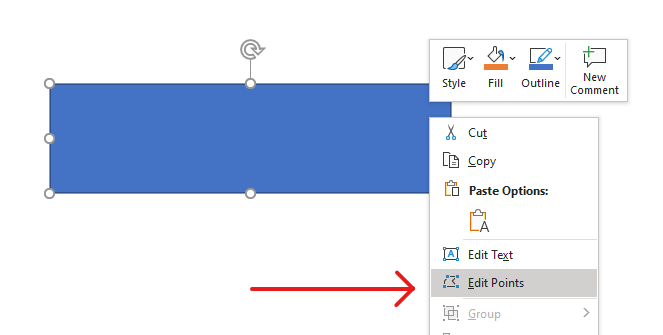
在開始透過編輯點編輯 PowerPoint 形狀之前,您可能需要了解以下關於形狀的要點:
- 形狀(或其路徑)可以是封閉的,也可以是開放的。
- 封閉的形狀沒有起點或終點。開放的形狀則有起始與結束點。
- 所有形狀至少由 2 個錨點組成,這些錨點以線段相連。
- 線段可以是直線或曲線。錨點決定線段的性質。
- 錨點可分為角點、直點或平滑點:
- 角點是兩條直線在角度處相交的點。
- 平滑點是兩個手柄位於同一直線上,且線段以平滑曲線相接的點。此情況下,兩個手柄與錨點之間的距離相等。
- 直點是兩個手柄位於同一直線上,線段仍以平滑曲線相接的點。此情況下,手柄與錨點的距離不必相等。
- 透過移動或編輯錨點(即改變線條角度),即可改變形狀的外觀。
為了透過編輯點編輯 PowerPoint 形狀,Aspose.Slides 提供了 GeometryPath 類別和 IGeometryPath 介面。
- 一個 GeometryPath 例項代表 IGeometryShape 物件的幾何路徑。
- 若要從
IGeometryShape例項取得GeometryPath,可使用 IGeometryShape::GetGeometryPaths 方法。 - 若要為形狀設定
GeometryPath,可使用以下方法:針對實心形狀使用 IGeometryShape::SetGeometryPath();針對複合形狀使用 IGeometryShape::SetGeometryPaths()。 - 若要新增線段,可使用 IGeometryPath 下的相關方法。
- 使用 IGeometryPath::set_Stroke() 與 IGeometryPath::set_FillMode() 方法,可設定幾何路徑的外觀。
- 透過 IGeometryPath::get_PathData() 方法,可將
GeometryShape的幾何路徑以路徑段陣列形式取得。 - 若需其他形狀幾何自訂選項,可將 GeometryPath 轉換為 GraphicsPath。
- 使用 GeometryPathToGraphicsPath 與 GraphicsPathToGeometryPath 方法(來自 ShapeUtil 類別)即可在 GeometryPath 與 GraphicsPath 之間互相轉換。
簡易編輯操作
以下 C++ 程式碼示範如何
在路徑末端加入直線
void LineTo(PointF point);
void LineTo(float x, float y);
在路徑的指定位置加入直線:
void LineTo(PointF point, uint32_t index);
void LineTo(float x, float y, uint32_t index);
在路徑末端加入三次貝茲曲線:
void CubicBezierTo(PointF point1, PointF point2, PointF point3);
void CubicBezierTo(float x1, float y1, float x2, float y2, float x3, float y3);
在路徑的指定位置加入三次貝茲曲線:
void CubicBezierTo(PointF point1, PointF point2, PointF point3, uint32_t index);
void CubicBezierTo(float x1, float y1, float x2, float y2, float x3, float y3, uint32_t index);
在路徑末端加入二次貝茲曲線:
void QuadraticBezierTo(PointF point1, PointF point2);
void QuadraticBezierTo(float x1, float y1, float x2, float y2);
在路徑的指定位置加入二次貝茲曲線:
void QuadraticBezierTo(PointF point1, PointF point2, uint32_t index);
void QuadraticBezierTo(float x1, float y1, float x2, float y2, uint32_t index);
將給定弧線附加至路徑:
void ArcTo(float width, float heigth, float startAngle, float sweepAngle);
關閉路徑目前的圖形:
void CloseFigure();
設定下一個點的位置:
void MoveTo(PointF point);
void MoveTo(float x, float y);
移除指定索引的路徑段:
void RemoveAt(int32_t index);
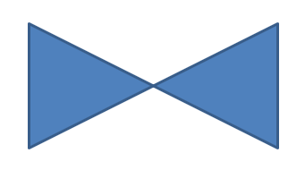
為形狀新增自訂點
- 建立一個 GeometryShape 例項,並將 ShapeType.Rectangle 設為類型。
- 從該形狀取得一個 GeometryPath 例項。
- 在路徑的兩個上方點之間加入新點。
- 在路徑的兩個下方點之間加入新點。
- 將路徑套用至形狀。
以下 C++ 程式碼示範如何為形狀加入自訂點:
SharedPtr<Presentation> pres = System::MakeObject<Presentation>();

SharedPtr<IShapeCollection> shapes = pres->get_Slides()->idx_get(0)->get_Shapes();
SharedPtr<GeometryShape> shape = System::ExplicitCast<GeometryShape>(shapes->AddAutoShape(ShapeType::Rectangle, 100.0f, 100.0f, 200.0f, 100.0f));

SharedPtr<IGeometryPath> geometryPath = shape->GetGeometryPaths()->idx_get(0);

geometryPath->LineTo(100.0f, 50.0f, 1);
geometryPath->LineTo(100.0f, 50.0f, 4);
shape->SetGeometryPath(geometryPath);
從形狀移除點
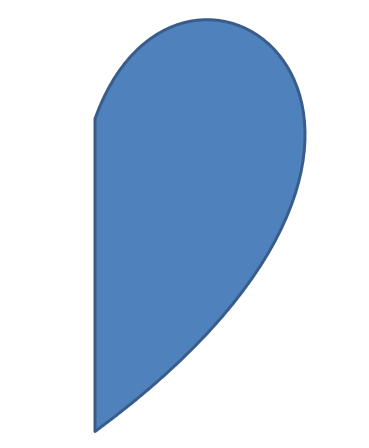
- 建立一個 GeometryShape 例項,並將 ShapeType.Heart 設為類型。
- 從該形狀取得一個 GeometryPath 例項。
- 移除該路徑的段落。
- 將路徑套用至形狀。
以下 C++ 程式碼示範如何從形狀移除點:
SharedPtr<Presentation> pres = System::MakeObject<Presentation>();

SharedPtr<IShapeCollection> shapes = pres->get_Slides()->idx_get(0)->get_Shapes();
SharedPtr<GeometryShape> shape = System::ExplicitCast<GeometryShape>(shapes->AddAutoShape(ShapeType::Heart, 100.0f, 100.0f, 300.0f, 300.0f));

SharedPtr<IGeometryPath> path = shape->GetGeometryPaths()->idx_get(0);
path->RemoveAt(2);
shape->SetGeometryPath(path);
建立自訂形狀
- 計算形狀的各個點座標。
- 建立一個 GeometryPath 例項。
- 使用這些點填充路徑。
- 建立一個 GeometryShape 例項。
- 將路徑套用至形狀。
以下 C++ 程式碼示範如何建立自訂形狀:
SharedPtr<List<PointF>> points = System::MakeObject<List<PointF>>();

float R = 100.0f, r = 50.0f;
int32_t step = 72;

for (int32_t angle = -90; angle < 270; angle += step)
{
    double radians = angle * (Math::PI / 180.f);
    double x = outerRadius * Math::Cos(radians);
    double y = outerRadius * Math::Sin(radians);
    points->Add(PointF((float)x + outerRadius, (float)y + outerRadius));

    radians = Math::PI * (angle + step / 2) / 180.0;
    x = innerRadiusr * Math::Cos(radians);
    y = innerRadiusr * Math::Sin(radians);
    points->Add(PointF((float)x + outerRadius, (float)y + outerRadius));
}

SharedPtr<GeometryPath> starPath = System::MakeObject<GeometryPath>();
starPath->MoveTo(points->idx_get(0));

for (int32_t i = 1; i < points->get_Count(); i++)
{
    starPath->LineTo(points->idx_get(i));
}

starPath->CloseFigure();

SharedPtr<Presentation> pres = System::MakeObject<Presentation>();

SharedPtr<IShapeCollection> shapes = pres->get_Slides()->idx_get(0)->get_Shapes();
SharedPtr<GeometryShape> shape = System::ExplicitCast<GeometryShape>(shapes->AddAutoShape(ShapeType::Rectangle, 100.0f, 100.0f, R * 2, R * 2));

shape->SetGeometryPath(starPath);

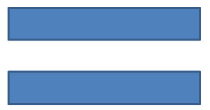
建立複合自訂形狀
- 建立一個 GeometryShape 例項。
- 建立第一個 GeometryPath 例項。
- 建立第二個 GeometryPath 例項。
- 將這兩條路徑套用至形狀。
以下 C++ 程式碼示範如何建立複合自訂形狀:
SharedPtr<Presentation> pres = System::MakeObject<Presentation>();

SharedPtr<IShapeCollection> shapes = pres->get_Slides()->idx_get(0)->get_Shapes();
SharedPtr<GeometryShape> shape = System::ExplicitCast<GeometryShape>(shapes->AddAutoShape(ShapeType::Rectangle, 100.0f, 100.0f, 200.0f, 100.0f));

SharedPtr<IGeometryPath> geometryPath0 = System::MakeObject<GeometryPath>();
geometryPath0->MoveTo(0.0f, 0.0f);
geometryPath0->LineTo(shape->get_Width(), 0.0f);
geometryPath0->LineTo(shape->get_Width(), shape->get_Height() / 3);
geometryPath0->LineTo(0.0f, shape->get_Height() / 3);
geometryPath0->CloseFigure();

SharedPtr<IGeometryPath> geometryPath1 = System::MakeObject<GeometryPath>();
geometryPath1->MoveTo(0.0f, shape->get_Height() / 3 * 2);
geometryPath1->LineTo(shape->get_Width(), shape->get_Height() / 3 * 2);
geometryPath1->LineTo(shape->get_Width(), shape->get_Height());
geometryPath1->LineTo(0.0f, shape->get_Height());
geometryPath1->CloseFigure();

shape->SetGeometryPaths(System::MakeArray<SharedPtr<IGeometryPath>>({ geometryPath0, geometryPath1 }));
建立具有曲線角的自訂形狀
以下 C++ 程式碼示範如何建立具有內縮曲線角的自訂形狀:
float shapeX = 20.f;
float shapeY = 20.f;
float shapeWidth = 300.f;
float shapeHeight = 200.f;

float leftTopSize = 50.f;
float rightTopSize = 20.f;
float rightBottomSize = 40.f;
float leftBottomSize = 10.f;

auto presentation = System::MakeObject<Presentation>();

auto childShape = presentation->get_Slides()->idx_get(0)->get_Shapes()->AddAutoShape(ShapeType::Custom, shapeX, shapeY, shapeWidth, shapeHeight);

auto geometryPath = System::MakeObject<GeometryPath>();

PointF point1(leftTopSize, 0.0f);
PointF point2(shapeWidth - rightTopSize, 0.0f);
PointF point3(shapeWidth, shapeHeight - rightBottomSize);
PointF point4(leftBottomSize, shapeHeight);
PointF point5(0.0f, leftTopSize);

geometryPath->MoveTo(point1);
geometryPath->LineTo(point2);
geometryPath->ArcTo(rightTopSize, rightTopSize, 180.0f, -90.0f);
geometryPath->LineTo(point3);
geometryPath->ArcTo(rightBottomSize, rightBottomSize, -90.0f, -90.0f);
geometryPath->LineTo(point4);
geometryPath->ArcTo(leftBottomSize, leftBottomSize, 0.0f, -90.0f);
geometryPath->LineTo(point5);
geometryPath->ArcTo(leftTopSize, leftTopSize, 90.0f, -90.0f);

geometryPath->CloseFigure();

childShape->SetGeometryPath(geometryPath);

presentation->Save(u"output.pptx", SaveFormat::Pptx);
判斷形狀幾何是否為封閉
封閉形狀是指其所有邊皆相連,形成單一無缺口的邊界。此類形狀可以是簡單的幾何圖形,也可以是複雜的自訂輪廓。以下程式碼示範如何檢查形狀幾何是否為封閉:
bool IsGeometryClosed(SharedPtr<IGeometryShape> geometryShape)
{
    bool isClosed = false;

    for (auto&& geometryPath : geometryShape->GetGeometryPaths())
    {
        auto dataLength = geometryPath->get_PathData()->get_Length();
        if (dataLength == 0)
            continue;

        auto lastSegment = geometryPath->get_PathData()[dataLength - 1];
        isClosed = lastSegment->get_PathCommand() == PathCommandType::Close;

        if (!isClosed)
            return false;
    }

    return isClosed;
}
將 GeometryPath 轉換為 GraphicsPath
- 建立一個 GeometryShape 例項。
- 建立一個屬於 System.Drawing.Drawing2D 命名空間的 GraphicsPath 例項。
- 使用 ShapeUtil 將 GraphicsPath 例項轉換回 GeometryPath。
- 將路徑套用至形狀。
以下 C++ 程式碼—依照上述步驟實作—展示 GeometryPath 轉換為 GraphicsPath 的過程:
SharedPtr<Presentation> pres = System::MakeObject<Presentation>();

SharedPtr<IShapeCollection> shapes = pres->get_Slides()->idx_get(0)->get_Shapes();
SharedPtr<GeometryShape> shape = System::ExplicitCast<GeometryShape>(shapes->AddAutoShape(ShapeType::Rectangle, 100.0f, 100.0f, 300.0f, 100.0f));

SharedPtr<IGeometryPath> originalPath = shape->GetGeometryPaths()->idx_get(0);
originalPath->set_FillMode(PathFillModeType::None);

SharedPtr<Drawing2D::GraphicsPath> graphicsPath = System::MakeObject<Drawing2D::GraphicsPath>();
graphicsPath->AddString(u"Text in shape", System::MakeObject<FontFamily>(u"Arial"), 1, 40.0f, PointF(10.0f, 10.0f), StringFormat::get_GenericDefault());

SharedPtr<IGeometryPath> textPath = ShapeUtil::GraphicsPathToGeometryPath(graphicsPath);
textPath->set_FillMode(PathFillModeType::Normal);

shape->SetGeometryPaths(System::MakeArray<SharedPtr<IGeometryPath>>({ originalPath, textPath }));

常見問題
取代幾何後,填充和輪廓會發生什麼變化?
樣式仍屬於形狀本身,只有輪廓會改變。填充和輪廓會自動套用至新的幾何。
如何正確旋轉自訂形狀以及其幾何?
使用形狀的 rotation 屬性;因為幾何綁定於形狀的座標系統,旋轉形狀時幾何也會同步旋轉。
我可以將自訂形狀轉換為圖像以「鎖定」結果嗎?